Introduction
Welcome! This is a book about multi-robot systems. Why? Because it's the future!
Robots are becoming more affordable, more capable, and more useful in many "real life" scenarios. As a result, we are seeing more and more robots that need to share spaces and work together to accomplish tasks. In this book, we will introduce the Robot Operating System 2 (ROS 2) as well as the Robot Middleware Framework (RMF), which is built on ROS 2 and tries to simplify the creation and operation of complex multi-robot systems.
This chapter describes the motivation and goals for ROS 2 and the RMF system for integrating multiple robots.
ROS 2
The Robot Operating System (ROS) is a set of software libraries and tools for building robot applications. From drivers to state-of-the-art algorithms, and with powerful developer tools, ROS has what you need for your next robotics project. And it’s all open source.
Since ROS was started in 2007, a lot has changed in the robotics and ROS community. ROS 1, originally just "ROS", began life as the development environment for the Willow Garage PR2 robot, a high-performance mobile manipulation platform intended for advanced research and development. The original goal of ROS was to provide the software tools users would need to undertake novel research and development projects with this robot. At the same time, the ROS 1 development team knew the PR2 would not be the only robot in the world, nor the most important, so they wanted ROS 1 to be useful on other robots, too. The original focus was on defining levels of abstraction (usually through message interfaces) that would allow much of the software to be reused elsewhere.
ROS 1 satisfied the PR2 use case, but also became useful on a surprisingly wide variety of robots. This included robots similar to the PR2, but also wheeled robots of all sizes, legged humanoids, industrial arms, outdoor ground vehicles (including self-driving cars), aerial vehicles, surface vehicles, and more. ROS 1 adoption also took a surprising turn, happening in domains beyond the mostly academic research community that was the initial focus. ROS-1-based products were coming to market, including manufacturing robots, agricultural robots, commercial cleaning robots, and others. Government agencies were also looking more closely at ROS for use in their fielded systems; NASA, for example, expected to run ROS on the Robonaut 2 deployed to the International Space Station.
All of these applications certainly grew the ROS platform in unexpected ways. Though it held up well, the ROS 1 team believed they could better meet the needs of the broader ROS community by tackling their new use cases head-on. And so, ROS 2 was born.
The initial goal of the ROS 2 project was to adapt to the changing landscape, leveraging what was great about ROS 1 and improving what wasn’t. But there was also a desire to preserve ROS 1 as it existed, to continue working and remain unaffected by the development of ROS 2. So, ROS 2 was built as a parallel set of packages that can be installed alongside and interoperate with ROS 1 (for example, through message bridges).
At the time of writing, we have reached the 13th and last official ROS 1 release, Noetic Ninjemys, and the first LTS release of ROS 2, Foxy Fitzroy.
A large and growing amount of ROS 2 resources can be found on the web. A great place to start is on the ROS Index page for ROS 2 and further along in this book in the ROS 2 chapter.
Enjoy your journey!
Robotics Middleware Framework (RMF)
For a moment, think of any large building. It could be a shopping mall, housing complex, university building, workplace, airport, hospital, hotel, and so on. Are items delivered within the building? Is the building floor cleaned regularly? For most buildings, the answer to both questions is "yes."
Now, let's think of what happens when robots start to perform those tasks. In today's robot marketplace, you can purchase excellent delivery robots, as well as excellent floor-cleaning robots. However, what if the floor is being cleaned at the same time that items are being delivered in the building? This situation is trivial when humans are performing the cleaning and delivery tasks: a quick glance between a delivery person pushing a cart and a custodian cleaning the floor is all it takes to quickly reach a compromise. One or both people will find a way to slightly alter the timing of their task to allow both tasks to be completed.
Unfortunately, robots are nowhere near as capable as humans at abstract reasoning, planning, and informal communication! This type of scenario is what the Robotics Middleware Framework (RMF) tries to help avoid. In today's marketplace, if all robots are purchased from the same manufacturer, the robots in such a single-vendor system will know of each other's existence and will avoid conflicting with each other. However, multi-vendor, multi-robot systems remain an open problem, and we expect that multi-vendor robot deployments will be the norm in all large buildings in the future. To address this situation, RMF provides a set of conventions, tools, and software implementations to allow multiple fleets of robots to interoperate with each other and with shared building infrastructure, such as lifts, doors, corridors, and other natural "bottlenecks" to traffic flows and tasks.
Without a framework for multi-vendor robotics in place, there can be significant but hidden risks for building operators and end users when they are forced to commit to a single system or platform provider. Hidden risks are likely to force an end user to limit their selection of future solutions from that a single provider to minimize operational risk and avoid redundant integration costs. As the scope and scale of robotic deployments increase, this problem is exacerbated, leaving the customer with the perception that there are no good options except to stay with their current provider, and preventing the use of robots from newer entrants to the marketplace.
Beyond the increased cost risk of scaling deployment with different providers, there is also the inherent conflict over shared resources such as lifts, doorways, corridors, network bandwidth, chargers, operations-center screen “real estate,” and human resources such as IT personnel and maintenance technicians. As robotic scale increases, it becomes more cumbersome for an operations team to consider managing a large, heterogeneous, multi-vendor robot environment.
These problem statements were the foundational motivations for the development of RMF.
In the previous "cleaning and delivery" scenario, RMF can act as a traffic controller to help the delivery robot and cleaning robot negotiate a way for both tasks to be accomplished, depending on the relative priority and importance of each task. If the cleaning task is urgent (perhaps a spill occurred in a busy corridor), RMF could route the delivery task through a different set of corridors. If the delivery task is time-critical, RMF could direct the cleaning robot to pause its work and move out of the way until the delivery robot clears the corridor. Of course, these solutions are obvious and could be easily hand-written for this particular "cleaning and delivery" corridor-sharing scenario. The challenge comes from trying to be generic across many scenarios, while also trying to be "future proof" to allow expansion to currently-unknown robots, applications, and task domains.
The rest of the book will dive into these details to show how RMF tries to foresee and prevent resource conflicts and improve the efficiency of multi-vendor, multi-robot systems. There is no magic here! All of the implementations are open-source and available for inspection and customization.
We would like to acknowledge the Singapore government for their vision and support to start this ambitious research and development project, "Development of Standardised Robotics Middleware Framework - RMF detailed design and common services, large-scale virtual test farm infrastructure, and simulation modelling". The project is supported by the Ministry of Health (MOH) and National Robotics Program (NRP).
Any opinions, findings and conclusions or recommendations expressed in this material are those of the author(s) and do not reflect the views of the NR2PO and MOH.
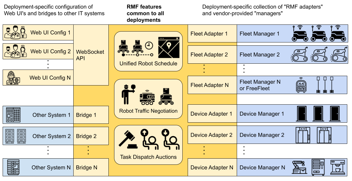
So what is RMF?
RMF is a collection of reusable, scalable libraries and tools building on top of ROS 2 that enable the interoperability of heterogeneous fleets of any type of robotic systems. RMF utilizes standardized communication protocols to infrastructure, environments and automation where robots are deployed to optimize the use of critical resources (i.e. robots, lifts, doors, passageways, etc). It adds intelligence to the system through resource allocation and by preventing conflicts over shared resources through the RMF Core which will be described in detail later in this book.
RMF is flexible and robust enough to operate over virtually any communications layer and integrate with any number of IOT devices. The architecture of RMF is designed in such a way to allow scalability as the level of automation in an environment increases. There are various ways for systems and users to interact with RMF via APIs and customizable user interfaces. Once deployed in an environment, RMF will save costs by allowing resources to be shared and integrations to be minimized. It is what robotic developers and robot customers have been looking for. In a nutshell, here is RMF:
How does RMF make the magic happen?
We will explore each of these functional areas in more detail in later chapters of this book, but for now we'd like to also introduce some of the other utilities helpful when developing and integrating with RMF.
RMF Demos
The demos are demonstrations of the capabilities of RMF in various environments. This repository serves as a starting point for working and integrating with RMF.
Traffic Editor
Traffic Editor is a GUI for creating and annotating floorplans for use in RMF.
Through Traffic Editor you are able to create traffic patterns for use in RMF and introduce simulation models to enhance your virtual simulation environments.
The .yaml files can be easily exported for use in Gazebo.
Free Fleet
Free Fleet is an open-source robot fleet management system for robot developers who do not have their own fleet manager or who would prefer to use and contribute to an open-source fleet management utility.
RMF Schedule Visualizer
This visualizer is an rviz-based rmf_core visualizer and control panel.
It is intended to be a functional tool for RMF developers.
RMF Web UI
rmf-web is a configurable web application that provides overall visualization and control over the RoMi-H system. The dashboard is by design more "operator-friendly" compared to the previously mentioned schedule visualizer.
RMF Simulation
rmf_simulation contains the simulation plugins to simulate RMF. Plugins are available in gazebo and ignition.
Simulation Assets
The open-source and freely distributable simulation assets are created and shared to accelerate simulation efforts.
For the latest instructions and updates please directly check the open-rmf/rmf repository.
Install ROS 2.
First, please follow the installation instructions for ROS 2. If you are on an Ubuntu 20.04 LTS machine (as recommended), here is the binary install page for ROS 2 Galactic on Ubuntu 20.04.
Setup Gazebo repositories
Setup your computer to accept Gazebo packages from packages.osrfoundation.org.
sudo apt update
sudo apt install -y wget
sudo sh -c 'echo "deb http://packages.osrfoundation.org/gazebo/ubuntu-stable `lsb_release -cs` main" > /etc/apt/sources.list.d/gazebo-stable.list'
wget https://packages.osrfoundation.org/gazebo.key -O - | sudo apt-key add -
Binary install
OpenRMF binary packages are available for Ubuntu Focal 20.04 for the Foxy, Galactic and Rolling releases of ROS 2. Most OpenRMF packages have the prefix rmf on their name, therefore, you can find them by them by searching for the pattern ros-<ro2distro>-rmf
apt-cache search ros-<ro2distro>-rmf
RMF Demos
A good way to install the rmf set of packages in one go is to install the one of the main RMF Demos packages. This will pull all the rest of the OpenRMF packages as a dependency. The core of RMF demos is contained on the rmf_demos package. However, if you want to install it with simulation support, you should install the rmf_demos_gz or rmf_demos_ign package which come with gazebo or ignition support respectively. To install the ROS 2 release with gazebo support package, you would run:
sudo apt install ros-<ro2distro>-rmf-demos-gz
Building from sources
If you want to get the latest developments you might want to install from sources and compile OpenRMF yourself.
Additional Dependencies
Install all non-ROS dependencies of OpenRMF packages,
sudo apt update && sudo apt install \
  git cmake python3-vcstool curl \
  qt5-default \
  -y
python3 -m pip install flask-socketio
sudo apt-get install python3-colcon*
Install rosdep
rosdep helps install dependencies for ROS packages across various distros. It can be installed with:
sudo apt install python3-rosdep
sudo rosdep init
rosdep update
Download the source code
Setup a new ROS 2 workspace and pull in the demo repositories using vcs,
mkdir -p ~/rmf_ws/src
cd ~/rmf_ws
wget https://raw.githubusercontent.com/open-rmf/rmf/main/rmf.repos
vcs import src < rmf.repos
Ensure all ROS 2 prerequisites are fulfilled,
cd ~/rmf_ws
rosdep install --from-paths src --ignore-src --rosdistro <ro2distro> -y
Compiling Instructions
NOTE: Due to newer changes in the source build, there might be conflicts and compilation errors with older header files installed by the binaries. Please remove the binary installations before building from source, using
sudo apt remove ros-<ro2distro>-rmf*.
Compiling on Ubuntu 20.04:
cd ~/rmf_ws
source /opt/ros/<ro2distro>/setup.bash
colcon build --cmake-args -DCMAKE_BUILD_TYPE=Release
NOTE: The first time the build occurs, many simulation models will be downloaded from Ignition Fuel to populate the scene when the simulation is run. As a result, the first build can take a very long time depending on the server load and your Internet connection (for example, 60 minutes).
Run RMF Demos
Demonstrations of OpenRMF are shown in rmf_demos.
Docker Containers
Alternatively, you can run RMF Demos by using docker.
Pull docker image from open-rmf/rmf github registry (setup refer here).
docker pull ghcr.io/open-rmf/rmf/rmf_demos:latest
docker tag ghcr.io/open-rmf/rmf/rmf_demos:latest rmf:latest
Run it!
docker run -it --network host rmf:latest bash -c "export ROS_DOMAIN_ID=9; ros2 launch rmf_demos_gz office.launch.xml headless:=1"
This will run rmf_demos in headless mode. Open this link with a browser to start a task.
(Experimental) User can also run rmf_demos in “non-headless” graphical form, via rocker.
Roadmap
A near-term roadmap of the entire OpenRMF project (including and beyond rmf_traffic) can be found in the user manual here.
Integrating with RMF
Instructions on how to integrate your system with OpenRMF can be found here.
Open sourced fleet adapters
A number of commercial robots have been integrated with RMF and links to their adapters are available below.
- Gaussian Ecobots
- OTTO Motors (and robots running the Clearpath Autonomy stack)
- Mobile Industrial Robots: MiR
- Temi- the personal robot
Help us add to this list!
A helpful starting point for integrating your fleet with RMF is the fleet_adapter_template package.
Demos
In this chapter, we will briefly demonstrate the capability of RMF with rmf_demos.
This will give users a brief understanding of the core features of RMF.
For the most updated rmf_demos run instruction, please refer to here.
First make sure, you have have installed the provided RMF demos from their Debian package:
# Demos example with gazebo simulator, use ros-foxy-rmf-demos-ign for ignition
sudo apt-get install ros-foxy-rmf-demos-gz
Run your desired demo. In this case we will run the airport terminal:
Before running the demo, we can ensure all required models are downloaded locally by:
ros2 run rmf_building_map_tools model_downloader rmf_demos_maps -s airport_terminal
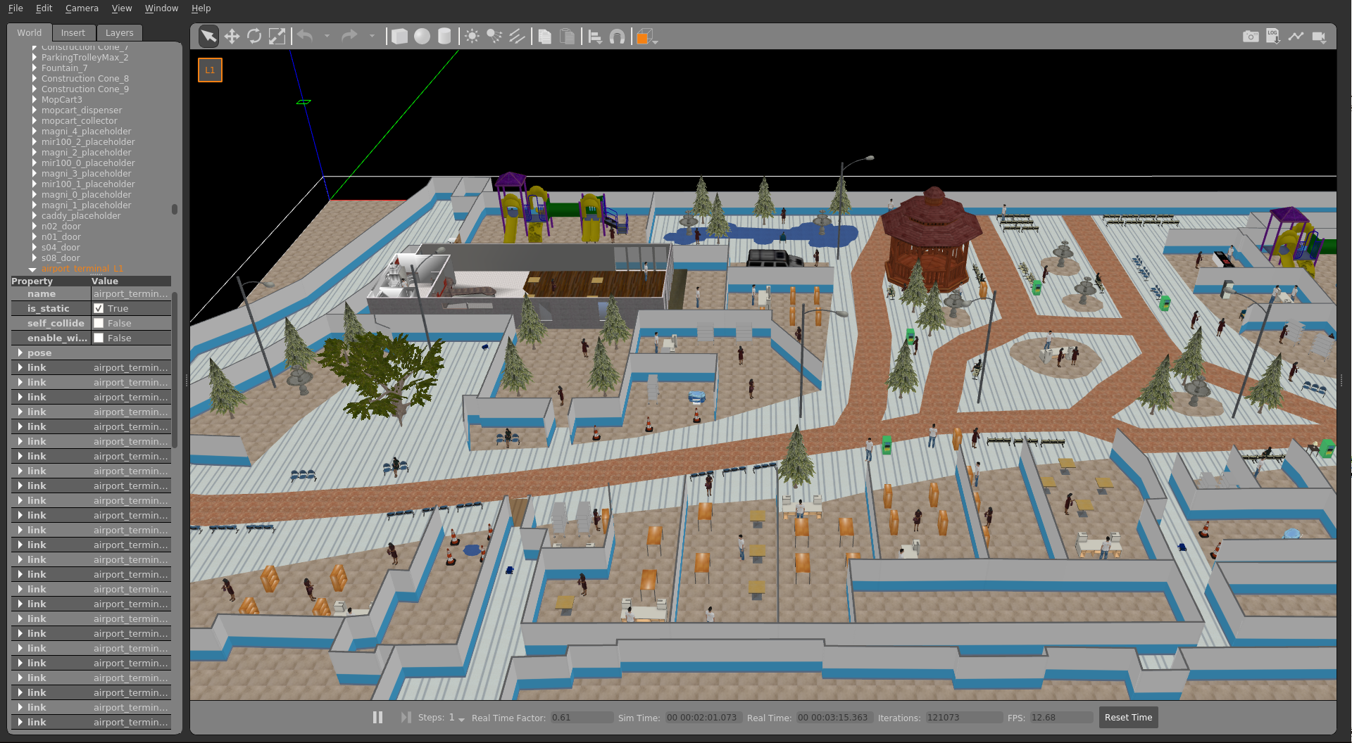
ros2 launch rmf_demos_gz airport_terminal.launch.xml
# or with ignition
ros2 launch rmf_demos_ign airport_terminal.launch.xml
Now you should be able to see the airport terminal with the robots in Gazebo:
The RMF Schedule Visualizer should have loaded in an rviz window. This canvas will display all integrated robots or infrastructure which are available to RMF.
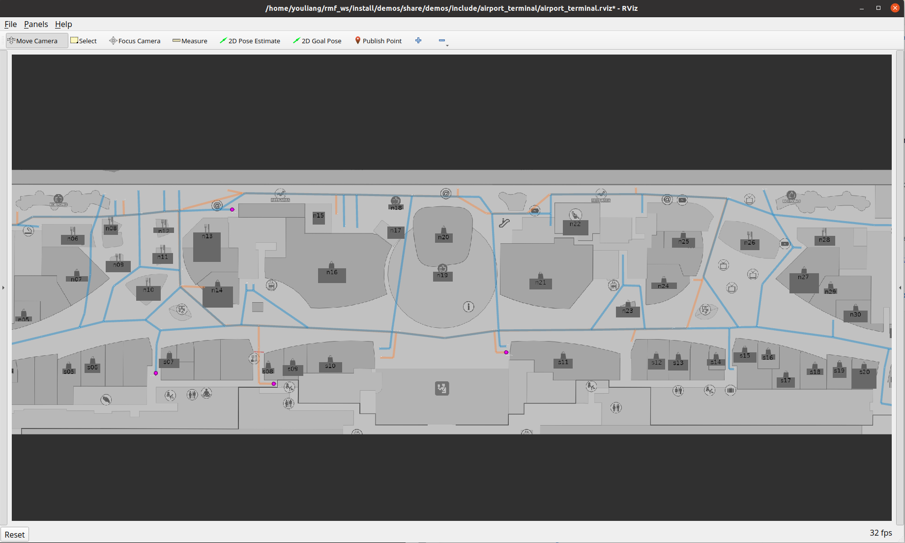
During a task request, instead of requiring the user to specify the robot name to complete a task, RMF will assign the task to the best robot.
RMF currently suports 3 types of task, namely: loop, delivery or clean . User can submit a task via CLI:
Loop Task
ros2 run rmf_demos_tasks dispatch_loop -s s07 -f n12 -n 3 --use_sim_time
Delivery Task
ros2 run rmf_demos_tasks dispatch_delivery -p mopcart_pickup -pd mopcart_dispenser -d spill -di mopcart_collector --use_sim_time
Clean Task
ros2 run rmf_demos_tasks dispatch_clean -cs zone_3 --use_sim_time
Now you can observe robots roaming around the airport space!
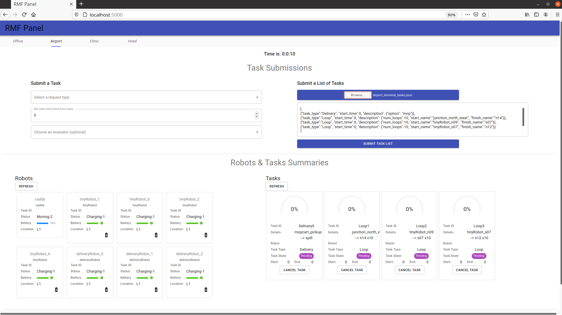
rmf_panel
Another way to observe and interact with RMF is via a web rmf_panel. Open the webpage: firefox https://open-rmf.github.io/rmf-panel-js/ or click here
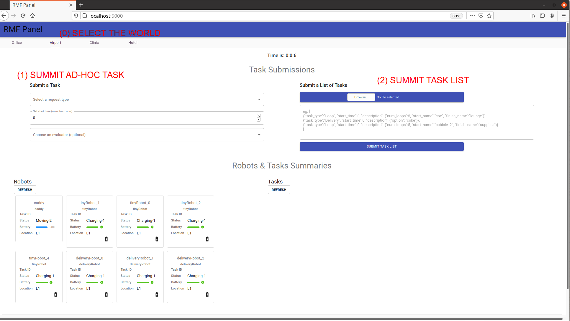
You can view the status of all the robots under RMF. To request a list of tasks, first select the Airport tab. User can choose to submit a (1) Adhoc task or (2) Task List.
Copy paste this to the Task List Box. (or open a file)
[{"task_type":"Delivery", "start_time":0, "description": {"option": "mop"}},
 {"task_type":"Loop", "start_time":0, "description": {"num_loops":10, "start_name":"junction_north_west", "finish_name":"n14"}},
 {"task_type":"Loop", "start_time":0, "description": {"num_loops":10, "start_name":"tinyRobot_n09", "finish_name":"s07"}},
 {"task_type":"Clean", "start_time":0, "priority":0, "description":{"cleaning_zone":"zone_2"}}
]
Then Click Submit to submit the list of tasks:
Now, sit back and enjoy.
Jump in, the water is fine!
So now you have an idea of what RMF is all about, it's time to jump in. We would suggest if you have not already that you take the time to review the RMF Demos repository and if you want a really quick overview of RMF then take a look at this Mock Airport Terminal video demo (Short film Oscar nominations most welcome). We hope you find RMF to be a useful tool to help you scale your robot deployments and operations and we look forward to the many improvements and contributions to come!
An Introduction to ROS 2
In this chapter we will cover the basics of Robot Operating System (ROS) and give you all the tools you need to build, debug, and understand robotic applications. This chapter is laid out from the most general concepts, necessary for decision makers to make sound decisions, to specific API references needed by engineers to develop new robotic applications. Somewhere in between high level concepts, and low level API commands lives the knowledge necessary for those maintaining and supporting multi-robot deployments in the field.
A good analogy to learning about ROS is the process of learning about motor vehicles. At the practical, day-to-day level, most people will learn how to start a vehicle and safely use it on a motorway. For these individuals, learning about the high level concepts behind ROS, along with application-specific commands is probably sufficient. Those who enjoy driving often choose to learn how to repair and maintain their vehicle. If this is your interest level we recommend learning the basics of the ROS command line interface. This will allow you to "check the oil" of your robotic systems and make sure everything is functioning correctly. Finally, if you are the type that would like to swap out the engine of your vehicle with something more powerful, or potentially build a wholly new vehicle from scratch, then the ROS API is the set of tools that will make this possible. Generally speaking, automotive engineers don't appear into the world fully formed, and the same is true for roboticists. It is advisable to work through each phase of understanding as you develop your skills with ROS.
Following from our analogy above the process of learning how to use robotic systems built on ROS can be divided roughly into four parts. This chapter works through these four parts of the process, using ROS 2. Subsequent chapters then build upon this knowledge and discuss the subtleties of specific applications. The four parts of this chapter are as follows.
-
Meta-discussion of the tools and resources available to help you in the learning process.
-
A high level discussion to the design patterns used in ROS. These patterns are roughly analogous to the subsystems you would find in a vehicle (engine, brakes, safety, climate control, etc).
-
A treatment of the command line interface (CLI) for ROS. The CLI is a set of programs for starting, inspecting, controlling, and monitoring a ROS robot. You can think of this topic as teaching you how check a robot's oil, and read the instrument panel.
-
An introduction to the ROS application programming interface. This section will show you how to create your own applications and modify existing software for your specific application.
While this book aims to cover the basics it should be made clear that ROS, like almost all software, is a moving target. Technology moves quickly, and while print media is helpful at delivering high fidelity instruction, that instruction can become rapidly outdated. For this reason we start this chapter with a meta-discussion of ROS resources that can be used to help you in your learning process.
ROS Kick Off
This chapter describes the avenues available for learning about and getting help with ROS, as well as how to get started by setting up and installing ROS.
Resources
The most up to date information about ROS can be found on the web. There are a myriad of resources on-line to help you out in your educational or practical journey. One thing to keep in mind is that ROS, like most software, has different versions, and the format and structure of commands and API calls may differ slightly between versions (although the developers try to keep things as stable as possible). This book is specifically written for ROS 2, Eloquent Elusor, or ROS Eloquent to be terse.
While newer or older versions of ROS 2 will be generally similar, it is worth paying attention to the distribution name or version number as there are changes between versions. A major version of ROS 2 generally corresponds to a distribution, denoted by a pair of matching letter adjectives and specific nouns related to specific genus and species of turtles (e.g. Eloquent Elusor, or Foxy Fitzroy). It is worth noting that ROS versions are usually pegged to specific version of Ubuntu Linux.
ROS grew up with the modern web, and as such it has a variety of resources and forums to help you solve problems and learn about the API and tools. Some of our web resources actually pre-date more widely used systems, so it helps to know where they are and how to use them. Probably the most important resource on the web for ROS users is answers.ros.org. Answers is a Q&A website similar to StackOverflow. Once you register for Answers you can ask or answer any ROS-related question. Be aware that asking a question well can be difficult. You should include as much information as possible to help others answer your question. This means you should include the ROS version, platform version, any debugging or stack trace information you have, and the offending source code.
Aside from ROS Answers you should check out both the ROS 2 tutorials and API documentation, and the ROS 1 wiki. The ROS 1 wiki can be found at wiki.ros.org. While it is specifically dedicated to ROS 1, much of the information is still relevant to ROS 2. If you are searching for up to date ROS 2 information, your go to source is the ROS 2 tutorials and API documents located at index.ros.org/doc/ros2. Many of the tutorials you will find in this book pull directly from this body of work. If you would like to find the latest ROS news and discuss various ROS features, the ROS Discourse forum at discourse.ros.org is your best bet. ROS discourse is the community hub where developers discuss their latest projects and debate the finer points of ROS development.
For ROS application developers there are a number of tools to help you connect with the broader ROS developer community. Open Robotics supports index.ros.org, which is an extended list of ROS packages sorted by version. If you are searching for a ROS driver for a particular piece of hardware, then the index is a great place to start. If you find a package with failing tests, or would like to know the build status of any ROS package, take a look at build.ros.org. Similarly, for un-indexed packages GitHub maintains a ROS code tag. This tag will allow you to search all of the tagged repositories that are publicly listed. At the time of writing there were close to 4000 repositories listed on GitHub, so there is a pretty good chance you'll find what you need.
Finally, there are a variety of unofficial resources that you should be aware of that can be useful, particularly if you want to keep yourself up to date with the latest ROS projects and features. Both Open Robotics and ROS maintain twitter feeds to share the latest news. We also have a yearly ROS developers conference called ROSCon; most talks are freely available on the web. There are a few other resources that can also be useful including the ROS subreddit and an "unofficial" ROS Discord.
Setting Up Your Computer
For this chapter we assume that you are working on a modern desktop with a discrete graphics card. While a graphics card isn't necessary for this chapter, later chapters will be graphics intensive and having one will greatly improve the end user experience. Moreover, this book assumes you are working with the Ubuntu Linux 18.04 operating system. While other operating systems are supported by ROS 2, all of the tutorials and instructions on this book assume you are running Linux. If instead you're using a Mac or Windows PC, you can install ROS 2 Eloquent Elusor using the instructions found on the ROS 2 installation instructions page. An alternative path for installation on Mac and PC is to using a virtual machine. Roughly the process for doing so is as follows:
- Install virtual machine software like Virtual Box or VMWare on your host machine.
- Create a virtual machine using the software, and install Desktop Ubuntu 18.04 Bionic Beaver from the Canonical website. Configure the installation as you wish.
- Now start your virtual machine and log in as a user. The directions below should be applicable.
For these initial tutorials we will be working with the pre-compiled ROS 2:
Eloquent Elusor desktop version. These directions follow directly from the
installation instructions found on the [Eloquent installation
page]https://index.ros.org/doc/ros2/Installation/Eloquent/Linux-Install-Debians/). To
run these commands you'll need a terminal window. To open a terminal in Ubuntu
18.04 click on the nine dots in the bottom left hand of the screen. A dialog
should appear. Enter the word terminal and click on the terminal icon to open
a terminal. Alternatively, you can press the control, alt, and 't' keys
simultaneously to open a terminal (we abbreviate this CTRL-ALT-T).
Setup Locale
The first step is to make sure you have a locale which supports UTF-8. What this means is that we
will check that the language used by your computer uses a particular format of
text. If you are in a minimal environment, such as a Docker container, the locale may be
something minimal like POSIX. We test with the following settings. It
should be fine if you're using a different UTF-8 supported locale.
sudo locale-gen en_US en_US.UTF-8
sudo update-locale LC_ALL=en_US.UTF-8 LANG=en_US.UTF-8
export LANG=en_US.UTF-8
Setup Sources
You will need to add the ROS 2 apt repositories to your system. Out of the box Ubuntu doesn't know where the ROS 2 binary programs live so we have to give it a secure location. To do this the computer will prompt you for your root password. For more technical readers we need to authorize the ROS GPG key with apt by typing the following command in the terminal:
sudo apt update && sudo apt install curl gnupg2 lsb-release
curl -s https://raw.githubusercontent.com/ros/rosdistro/master/ros.asc | sudo apt-key add -
Install ROS 2 Packages
The next steps for installing ROS is to do a system update (i.e. check for newer programs) and then install ROS Eloquent. To do this we run the following commands. Be aware that these commands will download a lot of data and may take awhile. It is best to run these commands on your home network.
sudo apt update
Desktop Install (Recommended): ROS, RViz, demos, tutorials.
sudo apt install ros-eloquent-desktop
Next we'll install a set of tutorials called TurtleSim. To do this we run
another apt command.
sudo apt install ros-eloquent-turtlesim
ROS 2 command line tools use argcomplete for autocompletion. If you want autocompletion, installing argcomplete is necessary. We're also going to install a few other tools to make our lives easier.
sudo apt install python3-argcomplete htop byobu
Check Your Installation
ROS uses environment variables to help keep track of what version of ROS is
running and where all the programs using ROS are on the computer. To set
these environment variables we source, or load, a bash script file. A bash
script file isn't magic; it is a series of commands to enter into the
terminal, just like the series of commands we just entered to setup ROS. It is
possible to have different versions of ROS running on a single computer. Using
the wrong version of ROS can lead to all sorts of problems and is a common
mistake for new users! If you are having problems, try sourcing the correct ROS
bash file. From now on, whenever you open a new terminal, you will
need to tell the computer which version of ROS to use. To set the necessary
environment variables for ROS you need to source a bash file every time you
open a new terminal. Yes, this is annoying, but it is a sound approach as it
makes the version of ROS you are using explicit. On Ubuntu 18.04 all versions of
ROS live in /opt/ros/. Inside this directory will be a programs and scripts
file to run ROS. To tell the operating system that we want to use ROS Eloquent
we simply source the ROS Eloquent setup.bash file using the command below:
source /opt/ros/eloquent/setup.bash
Once that command runs, your terminal should be ready to run a ROS program. Let's
test our installation by running two small ROS programs called talker and
listener. These two programs will send data back and forth using ROS to
perform the communication. One program was written in C++ and the other in
Python. Running these two different programs is a quick and easy way to check
that your ROS system is configured correctly. To start the talker run the following command:
source /opt/ros/eloquent/setup.bash
ros2 run demo_nodes_cpp talker
If everything is working correctly you should see something like the following:
[INFO] [talker]: Publishing: 'Hello World: 1'
[INFO] [talker]: Publishing: 'Hello World: 2'
[INFO] [talker]: Publishing: 'Hello World: 3'
....
Now, let's fire up the listener. We're going to use a Python listener in this
example to make sure we installed Python correctly. First we will need a second terminal. We can
open a new terminal tab by entering CTRL-SHIFT-T in our terminal. We can also
create a wholly new terminal by pressing CTRL-ALT-T. Pick whatever works best
for you. Now in your new terminal source your bash file and run the following
command:
source /opt/ros/eloquent/setup.bash
ros2 run demo_nodes_py listener
If everything is working correctly you should see something like the following:
[INFO] [listener]: I heard: [Hello World: 264]
[INFO] [listener]: I heard: [Hello World: 265]
[INFO] [listener]: I heard: [Hello World: 266]
Now that we have tested our ROS installation we can stop these two programs. In
ROS most programs run in infinite loops until the robot is shut down. To stop
these programs we navigate to the terminal running the program and press the
Ctrl and C keys simultaneously. We call this combo CTRL-C and you can use
it to stop just about any program in a terminal. Use it to stop the talker and
listener programs.
ROS Concepts and Design Patterns
As we said, learning about ROS is similar to learning about an automobile. In fact, a car is a lot like a robot (and sometimes it really is a robot; see the large and active self-driving vehicle industry). A modern automobile comprises many parts that are connected to each other. The steering wheel is connected to the front axle, the brake pedal is connected to the brake calipers, the oxygen sensor is connected to the fuel injectors, and so on. From this perspective, a car is a distributed system: each part plays a well-defined role, communicating (whether electrically or mechanically) as needed with other parts, and the result of that symphony-like coordination is a working vehicle.
A key philosophical tenet of ROS is that robotics software should also be designed and developed as a distributed system. We aim to separate the functions of a complex system into individual parts that interact with each other to produce the desired behavior of that system. In ROS we call those parts nodes and we call the interactions between them topics (and sometimes services, but we will get to that).
The ROS Communication Graph
Imagine we are building a wheeled robot that chases a red ball. This robot needs a camera with which to see the ball, a vision system to process the camera images to figure out where the ball is, a control system to decide what direction to move, and some motors to move the wheels to allow it to move toward the ball. Using ROS we might construct the system like so:
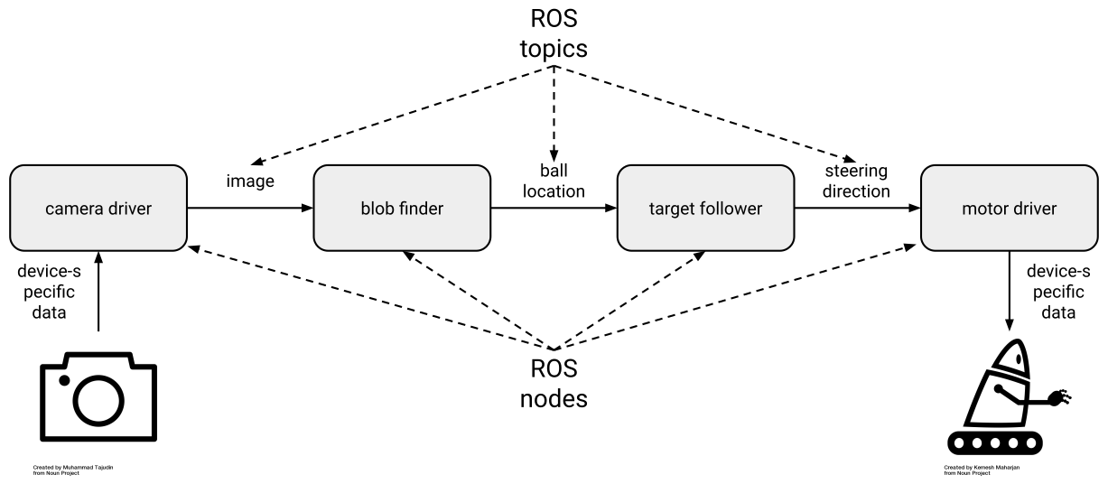
This design separates the software into four ROS nodes: two device drivers and two algorithms. Those nodes communicate with each other as shown, via three ROS topics. We call this structure a ROS communication graph: the nodes are the graph vertices and the topics are the graph edges. You can tell a lot about a ROS system by examining its communication graph.
The camera driver node is responsible for handling the details of interacting with the physical camera, which might happen through a custom USB protocol, through a vendor-provided library, or in some other way. Whatever those details, they are encapsulated inside the camera driver node, which presents a standard topic interface to the rest of the system. As a result, the blob finder node does not need to know anything about the camera; it simply receives image data in a standard format that is used for all cameras in ROS. The output of the blob finder is the detected location of the red ball, also in a standard format. Then the target follower node can read in the ball location and produce the steering direction needed to move toward the ball, again in a standard format. Finally, the motor driver node's responsibility is to convert the desired steering direction into the specific instructions necessary to command the robot's wheel motors accordingly.
Publish-Subscribe Messaging: Topics and Types
With the example of the ball-chasing robot in mind, we can add some terminology to describe what is happening as the system operates. First, the ROS communication graph is based on a well-known pattern called publish-subscribe messaging, or simply pub-sub. In a pub-sub system, as the name implies, data are sent as messages from publishers to subscribers. A publisher may have zero, one, or multiple subscribers listening to its published messages. Messages may be published at any time, making the system asynchronous.
In ROS, nodes publish and subscribe via topics, each of which has a name and a
type. A publisher announces that it will be publishing data by advertising a
topic. For example, the camera driver node may advertise a topic named /image
with type sensor_msgs/Image. If the blob finder node subscribes to a topic
with the same name and type, then the two nodes find each other and establish a
connection over which image messages can get from the camera driver to the blob
finder (the nodes find each other and establish those connections in a process
called discovery, which will be covered in detail later in this book). Each
message that flows across the /image topic will be of type
sensor_msgs/Image.
A single node can be (and often is) both a publisher and a subscriber. In our example, the blob finder subscribes to image messages and publishes ball location messages. Similarly the target follower subscribes to ball location messages and publishes steering direction messages.
A topic's type is very important. In fact, taken together, the ROS types are
among the most valuable aspects of the entire platform. First, a type tells you
the syntax: which fields, of which types, does the message contain? Second, it
tells you the semantics: what do those fields mean and how should they be
interpreted? For example, a thermometer and a pressure sensor might produce what
appear to be the same data: a floating-point value. But in ROS, a well-designed
thermometer driver node would publish one clearly defined type (say,
sensor_msgs/Temperature), while a pressure sensor driver node would publish
another (say, sensor_msgs/FluidPressure).
We always advise the use of semantically meaningful message types.
For example, ROS provides simple message types like std_msgs/Float64, which
contains a single 64-bit floating-point field called data. But you should only
use that sort of generic type for rapid prototyping and experimenting. When you
build a real system, even if something like std_msgs/Float64 could get the job
done on syntax, you should instead find or define a message that also matches
the semantics of your application.
Why Publish-Subscribe?
Given that it comes with additional complexity (nodes, topics, types, etc.), it is reasonable to ask why ROS follows the pub-sub pattern. After more than a decade of building and deploying ROS-based robot systems, we can identify several key benefits:
- Substitution: If we decide to upgrade the robot's camera, we need only modify or replace the camera driver node. The rest of the system never knew the details of the camera anyway. Similarly, if we find a better blob finder node, then we can just swap it in for the old one and nothing else changes.
- Reuse: A well-designed blob finder node can be used today on this robot to chase the red ball, then reused tomorrow on a different robot to chase an orange cat, and so on. Each new use of a node should require only configuration (no code) changes.
- Collaboration: By cleanly separating concerns between nodes, we let our blob finder expert do their work independently of the target follower expert, with neither of them bothering the device driver expert. It is often the case that a robot application requires the combined expertise of many people, and it would be difficult to overstate the importance of ensuring that they can each contribute confidently and efficiently.
- Introspection: Because the nodes are explicitly communicating with each other via topics, we can listen in. So when the robot fails to chase the red ball, and we think that the problem is in the blob finder, we can use developer tools to visualize, log, and play back that node's inputs and outputs. The ability to introspect a running system in this way is instrumental to being able to debug it.
- Fault tolerance: Say that the target follower node crashes because of a bug. If it is running in its own process, then that crash will not bring down the rest of the system, and we can get things working again by just restarting the target follower. In general with ROS we have the choice to run nodes in separate processes, which allows for such fault tolerance, or run them together in a single process, which can provide higher performance (and of course we can mix and match the two approaches).
- Language independence: It can happen that our blob finder expert writes their computer vision code in C++, while our target follower expert is dedicated to Python. We can accommodate those preferences easily by just running those nodes in separate processes. In ROS, it is perfectly reasonable, and in fact quite common, to mix and match the use of languages in this way.
Beyond Topics: Services, Actions, and Parameters
Most ROS data flows over topics, which we introduced in the previous sections. Topics are best for streaming data, which includes a lot of the common use cases in robotics. For example, going back to our ball-chasing robot, most cameras will naturally produces a stream of images at some rate, say, 30Hz. So it makes sense for the camera driver to publish the ROS messages containing those images just as soon as they're received. Then the blob finder will be receiving image messages at 30Hz, so it might as well publish its ball location messages at the same rate, and so on, through the target follower to the motor driver. We might say that such a systems is clocked from the camera: the data rate of the primary sensor, the camera in this case, drives the rate of computation of the system, with each node reacting in to receipt of messages published via topics by other nodes. This approach is fairly common and is appropriate for systems like our ball-chasing robot. There is no reason to do any work until you have a new camera image, and once you have one you want to process it as quickly as possible and then command an appropriate steering direction in response.
(We are making various simplifying assumptions, including that there is sufficient computational capacity to run all the nodes fast enough to keep up with the camera's data rate; that we do not have a way to predict where the ball is going in between camera frames; and that the motors can be commanded at the same rate the camera produces images.)
Services
So topics get the job done for the basic ball-chasing robot. But now say that we want to add the ability to periodically capture an ultra-high-resolution image. The camera can do it, but it requires interrupting the usual image stream that we rely on for the application, so we only want it to happen on demand. This kind of interaction is a poor fit for the publish-subscribe pattern of a topic. Fortunately, ROS also offers a request-reply pattern in a second concept: services.
A ROS service is a form of remote procedure call (RPC), a common concept in distributed systems. Calling a ROS service is similar to calling a normal function in a library via a code API. But because the call may be dispatched to another process or even another machine on the network, there is more to it than just copying pointers around. Specifically, a ROS service is implemented using a pair of ROS messages: a request and a reply. The node calling the service populates the request message and sends it to the node implementing the service, where the request is processed, resulting in a reply message that is sent back.
We might implement the new high-res snapshot capability like so:
- Define a new service type. Because services are less widely used than
topics, there are relatively few "standard" service types predefined.
In our case, the new service's request message might include the desired
resolution of the snapshot. The request message could be a standard
sensor_msgs/Image. - Implement the service. In the camera driver, we would advertise the newly defined service so that when a request is received, the usual image-handling is interrupted temporarily to allow the device interaction necessary to grab one high-res snapshot, which is then packed into a reply message and sent back to the node that called the service.
- Call the service. In the target follower node, we might add a timer so that every 5 minutes, it calls the new service. The target follower would receive the high-res snapshot in response to each call, and could then, say, add it to a photo gallery on disk.
In general, if you have a need for infrequent, on-demand interactions among nodes, ROS services are a good choice.
Actions
Sometimes, when building robot control systems, there is a need for an interaction that looks like request-reply, but that can require a lot of time between the request and the reply. Imagine that we want to wrap up our ball-chasing control system into a black box that can be invoked as part of a larger system that makes the robot play football. In this case, the higher level football controller will periodically want to say, "please chase the red ball until you have it right in front of you." Once the ball is in front of the robot, the football controller wants to stop the ball-chasing controller and invoke the ball-catching controller.
We could achieve this kind of interaction with a ROS service. We could define a chase-ball service and implement it in the target follower. Then the football controller could call that service when it wants the ball chased. But ball-chasing may take quite some time to complete, and it may fail to complete. Unfortunately, after calling the chase-ball service, the football controller is stuck waiting for the reply, similar to the situation in which you call a long-running function in code. The football controller does not know how well (or poorly) the chase is going, and it cannot stop the chase.
For such goal-oriented, time-extended tasks, ROS offers a third concept that is similar to services but more capable: actions. A ROS action is defined by three ROS messages: a goal, a result, and feedback. The goal, sent once by the node calling the action to initiate the interaction, indicates what the action is trying to achieve; for ball-chasing it might be the minimum required distance to the ball. The result, sent once by the node implementing the action after the action is complete, indicates what happened; for ball-chasing it might be final distance to the ball after the chase. The feedback, sent periodically by the node implementing the action until it is complete, updates the caller on how things are going; for ball-chasing it might be the current distance to the ball during the chase. In addition, actions are cancelable, so the football controller can decide to give up and move onto another tactic if the chase is taking too long or if the feedback messages are showing that there is little chance of success.
In general, if you want to support on-demand, long-running behaviors, ROS actions are a good choice.
Parameters
Any nontrivial system requires configuration, and ROS is no exception.
When we start our robot's motor driver node, how do we tell it to
connect to the motors via /dev/ttyUSB1? We do not want to hard-code
that information into the node, because on the next robot it might be
/dev/ttyUSB0 instead. ROS addresses such configuration needs via a
fourth concept: parameters. A ROS parameter is what you might expect:
a named, typed, place to store a piece of data. For example, the motor
driver node may define a parameter called serial_port with type
string. When it starts up, the node would use the value of that
parameter to know which device to open to get to the motor system.
ROS parameters can be set in a few ways:
- Defaults. A ROS node that uses a parameter must embed in its code some default value for that parameter. In the case that nothing else in the system sets the parameter value explicitly, the node needs some value to work with.
- Command-line. There is standard syntax for setting parameter values on the command-line when launching a node. Values set in this manner override defaults in the code.
- Launch files. When launching nodes via the
launchtool instead of manually via the command-line, you can set parameter values in the launch file. Values set in this manner override defaults in the code. - Service calls. ROS parameters are dynamically reconfigurable via a standard ROS service interface, allowing them to be changed on the fly, if the node hosting the parameters allows it. Values set in this manner override whatever previous values were set.
For most nodes, parameter management is relatively simple: define a
handful of parameters, each with a reasonable default; retrieve the
parameters' values at startup, which accounts for changes made via
command-line or launch file, then begin execution and disallow future
changes. This pattern makes sense for the motor driver, which needs to
know which /dev/ttyUSB device file to open at startup, and does not
support changing that setting later. But there are cases that require
more sophisticated handling. For example, the blob finder node may
expose as parameters a variety of thresholds or other settings that
configure how it identifies the red ball in images. These kinds of
settings can be changed on the fly, which the target follower might want
to do, based on how well the chase is going. In this case the blob
finder needs to be sure to use the latest values for its parameters,
knowing that they may have been changed by another node.
In general, when you want to store stable, but possibly changeable, configuration information in a node, ROS parameters are a good choice.
Asynchrony in Code: Callbacks
Throughout ROS, you will see a common pattern in the code, which is the use of callback functions, or simply callbacks. For example, when subscribing to a topic, you supply a callback, which is a function that will be invoked each time your node receives a message on that topic. Similarly, when you advertise a service, you supply a callback that is invoked when the service is called. The same goes for actions (for handling of goals, results, and feedback) and parameters (for handling of setting new values).
Programming with callbacks is not familiar to everyone. It differs from the
standard sequential presentation of programming, in which you write a main()
function that does A, then B, then C, and so on. By contrast, in ROS (and in
most systems that focus on data-processing and/or control), we follow an
event-based pattern. In this pattern, we do A whenever X happens, B whenever Y
happens, and so on.
A common structure for a ROS node is the following:
- Get parameter values. Retrieve the node's configuration, considering defaults and what may have been passed in from outside.
- Configure. Do whatever is necessary to configure the node, like establish connections to hardware devices.
- Set up ROS interfaces. Advertise topics, services, and/or actions, and subscribe to services. Each of these steps supplies a callback function that is registered by ROS for later invocation.
- Spin. Now that everything is configured and ready to go, hand control over to ROS. As messages flow in and out, ROS will invoke the callbacks you registered.
Following this structure, a main() function in a ROS node is often very
short: initialize and configure everything, then call a spin function to let
ROS take over. When you are trying to understand what is happening in a ROS
node, look in the callbacks; that is where the real work is happening.
The ROS Command Line Interface
The ROS command line interface, or CLI for short, is a set of programs for starting, inspecting, controlling, and monitoring a ROS robot. The best way to think of the CLI is a collection of small and simple programs that allow you perform basic tasks in ROS. Drawing from our car analogy, the CLI can be thought of as the subsystems of a vehicle: the breaks, the transmission, the window wipers, all of the smaller parts that are composed together to build the larger vehicle. What we'll show you in this section is how to turn on the car, put it in gear, turn on the radio, and perhaps check your oil to perform routine maintenance. The ROS 2 CLI draws heavily from the Unix/Linux philosophy of small programs that can be composed together. If you are familiar with the command line interface found in Unix and Linux, or to a lesser extent in MacOS or Windows, you'll feel right at home.
The ROS command line tools draw heavily from the design patterns mentioned in the previous section, and directly interface with the APIs we will address in the next section. The CLI interface is at its core just a set of simple tools built from the ROS 2 API; this API is simply an implementation of the high-level patterns we discussed in the previous section. If your goal is to simply interface with a particular piece of software written using ROS, the CLI interface is the way you will go about starting, stopping, and controlling the underlying ROS software. For more advanced users these tools will allow you to study a ROS system by exploring the underlying software processes in the system.
There are only two things you need to memorize from this section. The first command simply tells your computer that you are using ROS, and what version of ROS you want to use. Let's take a look at the magic command:
source /opt/ros/eloquent/setup.bash
If everything is working correctly, this command should simply return. Nothing happens that you can see, but underneath the hood you've just told this particular shell that you are using ROS 2 Eloquent Elusor, and where all the ROS programs and files live. You should plan on doing this every time you want to use ROS. The most common mistake new users have is not running this command. If you're not sure if you ran the command in a shell, that's okay. The command is idempotent; running it twice in a row won't break anything. You can run it a million times in a row and it won't make any difference.
The other command you need to commit to memory is ros2. Almost everything in
the ROS 2 CLI starts with ros2. Go ahead and try it in the same shell where you just sourced the setup file.
If everything is working correctly you should see the following:
$ ros2
usage: ros2 [-h] Call `ros2 <command> -h` for more detailed usage. ...

ros2 is an extensible command-line tool for ROS 2.

optional arguments:
  -h, --help            show this help message and exit

Commands:
  action     Various action related sub-commands
  component  Various component related sub-commands
  daemon     Various daemon related sub-commands
  doctor     Check ROS setup and other potential issues
  interface  Show information about ROS interfaces
  launch     Run a launch file
  lifecycle  Various lifecycle related sub-commands
  msg        Various msg related sub-commands
  multicast  Various multicast related sub-commands
  node       Various node related sub-commands
  param      Various param related sub-commands
  pkg        Various package related sub-commands
  run        Run a package specific executable
  security   Various security related sub-commands
  service    Various service related sub-commands
  srv        Various srv related sub-commands
  topic      Various topic related sub-commands
  wtf        Use `wtf` as alias to `doctor`

  Call `ros2 <command> -h` for more detailed usage.
From this one command you can figure out what every single ROS 2 CLI program does and
how to use it. The ROS 2 CLI has a syntax just like most languages. All ROS CLI commands start
with ros2, followed by a command. After the command any number of other things
can come; you can append --help or -h to see the documentation and find out what arguments any of the commands are expecting.
The rest of this section just walks through each of the commands one by one.
Writing commands using the command line is tricky and error
prone. There are a couple of tools you can use to make the process much
smoother. The first is the TAB key, which attempts to auto complete whatever you type.
It can't read your mind, but for common command combinations you usually only need to type the
first one or two letters. Another tool is the up arrow key. When you use the
command line sometimes you mistype a command, or need to rerun a
command. Pressing the up key will cycle through the previous commands which you
can modify and rerun as needed.
Running Your First ROS Program
Let's get started with our first ROS CLI command. The first command we'll visit
is run. Let's start by looking at the documentation for the run command:
$ ros2 run
usage: ros2 run [-h] [--prefix PREFIX] package_name executable_name ...
ros2 run: error: the following arguments are required: package_name, executable_name, argv
To get more complete information about a ROS 2 command, simply ask the command for help by
adding --help to the command. Let's try that again:
$ ros2 run --help
usage: ros2 run [-h] [--prefix PREFIX] package_name executable_name ...

Run a package specific executable

positional arguments:
  package_name     Name of the ROS package
  executable_name  Name of the executable
  argv             Pass arbitrary arguments to the executable

optional arguments:
  -h, --help       show this help message and exit
  --prefix PREFIX  Prefix command, which should go before the executable.
                   Command must be wrapped in quotes if it contains spaces
                   (e.g. --prefix 'gdb -ex run --args').
We can see that ros2 run is the
command to, "Run a package specific executable." In ROS 2 collections of ROS
software are gathered into logical units called packages. Each package
contains all of the source code for the package as a variety of other data that
tells ROS how to build and compile the package and the names of all the
programs, also called executables, that can be found in the package. The line
below the description then gives the positional arguments for the
package. Positional arguments are the words and values that come after ros2
and the command you run. In this case the syntax for the command sentence we
want to write is as follows:
ros2 run <package name> <program/executable name> <args>
There is one piece of missing information here. What is this argv that the
command is asking for? The argv element is programmer short hand for variable
arguments, and it simply means, "some number of additional arguments that are
determined by the executable". It is worth noting that a program can have zero
arguments and you can just leave it blank. This is actually how a lot of
programs work. For example, say we had a package
called math, and an executable called add that takes in two numbers and
returns the result. In this case argv would be the two numbers to add. The
final command would look like:
ros2 run math add 1 2
Finally, below the positional arguments we have optional arguments. You don't need to included them, unless you need to.
Now that we've looked into our help file let's run our first ROS program. For
these tutorials we're going to use a package called turtlesim, and the program
we want to run is turtlesim_node. Let's run this program (remember your tab
complete!). Your command should look like the following:
ros2 run turtlesim turtlesim_node
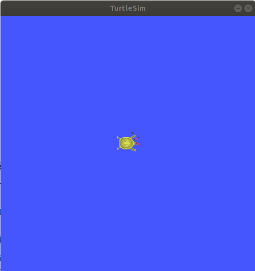
If everything goes smoothly you should see the following:
[INFO] [turtlesim]: Starting turtlesim with node name /turtlesim
[INFO] [turtlesim]: Spawning turtle [turtle1] at x=[5.544445], y=[5.544445], theta=[0.000000]
A window should also pop up with a cute little turtle that looks like the one below:
The real power in ROS isn't that it can run a program, it is that it can run lots of programs all at the same time, all talking together to control a robot, or multiple robots, all working together. To illustrate this let's run a second ROS program that makes our little turtle move around.
To do this we'll first open a new terminal (using CTRL-SHIFT-T). Next we'll
tell that terminal that we want to use ROS Eloquent by using the source command.
Finally, we'll run another program in the
turtlesim package to draw a square. See if you can find the program
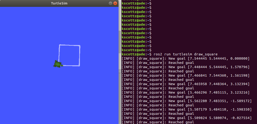
yourself (hint: use TAB). If everything works you should have typed the following, and the
following output should be visible:
$ source /opt/ros/eloquent/setup.bash
$ ros2 run turtlesim draw_square
[INFO] [draw_square]: New goal [7.544445 5.544445, 0.000000]
[INFO] [draw_square]: Reached goal
[INFO] [draw_square]: New goal [7.448444 5.544445, 1.570796]
[INFO] [draw_square]: Reached goal
Your screen should look roughly like this:
It is worth noting that you can stop any ROS program by pressing the Ctrl and
C keys at the same time in the terminal; we call this CTRL-C (note that
CTRL-SHIFT-C and CTRL-SHIFT-V are responsible for copy and paste in a Linux terminal).
Feel free to try it out. Start and stop the programs, and then
restart them before moving on.
ROS Topics
We now have two ROS 2 programs running from the turtlesim package.
There is turtle_node that opens our turtle simulation, and draw_square
that makes the turtle in turtle_node move around. How are these two
programs communicating?
ROS programs, also called nodes, communicate over topics on the ROS message bus. ROS topics use namespaces to distinguish themselves. For example, in a vehicle running ROS, the positions of each wheel may be organized as follows:
/wheels/front/driver/velocity
/wheels/front/passenger/velocity
/wheels/rear/driver/velocity
/wheels/rear/passenger/velocity
The key thing to realize about topics is that the data they contain is dynamic, meaning it changes
constantly. In our vehicle example the velocity of each wheel might be measured
one thousand times a second or more. Since the data in a ROS topic is constantly
changing, an important distinction for a topic is whether the topic is "creating"
or as we like to say in ROS publishing, or if it is reading the data, what we call
subscribing to the topic. Many ROS nodes subscribe to one set of topics,
process that input data, and then publish to another set of topics.
Let's return to our turtlesim example and see if we can use the ROS CLI to
understand the topics, publishers, and subscribers.
To see sub commands and syntax for the topic command, we'll run: ros2 topic --help.
This command outputs the following:
$ ros2 topic --help
usage: ros2 topic [-h] [--include-hidden-topics]
                  Call `ros2 topic <command> -h` for more detailed usage. ...

Various topic related sub-commands

optional arguments:
  -h, --help            show this help message and exit
  --include-hidden-topics
                        Consider hidden topics as well

Commands:
  bw     Display bandwidth used by topic
  delay  Display delay of topic from timestamp in header
  echo   Output messages from a topic
  find   Output a list of available topics of a given type
  hz     Print the average publishing rate to screen
  info   Print information about a topic
  list   Output a list of available topics
  pub    Publish a message to a topic
  type   Print a topic's type

  Call `ros2 topic <command> -h` for more detailed usage.
There are quite a
few sub commands; we won't discuss all of them, but let's look closely at a few.
Sub commands have their
own help command. Why don't we examine the list command. Repeating our command
pattern let's try running ros2 topic list --help.
usage: ros2 topic list [-h] [--spin-time SPIN_TIME] [-t] [-c]
                       [--include-hidden-topics]

Output a list of available topics

optional arguments:
  -h, --help            show this help message and exit
  --spin-time SPIN_TIME
                        Spin time in seconds to wait for discovery (only
                        applies when not using an already running daemon)
  -t, --show-types      Additionally show the topic type
  -c, --count-topics    Only display the number of topics discovered
  --include-hidden-topics
                        Consider hidden topics as well
As indicated at the top of this command help file, ros2 topic list will
"Output a list of available topics." There appears to be a variety of
optional arguments that we don't need to include if we don't want to. However,
the -t, --show-types line looks interesting. It is worth noting that command
arguments, sometimes called flags, can have two types. A short form indicated
with a single dash ("-"), and a long form indicated by a double dash
("--"). Don't worry, despite looking different both versions of the argument do
the same thing. Let's try running this command, sub command pair with the
-show-types argument.
$ ros2 topic list --show-types
/parameter_events [rcl_interfaces/msg/ParameterEvent]
/rosout [rcl_interfaces/msg/Log]
/turtle1/cmd_vel [geometry_msgs/msg/Twist]
/turtle1/color_sensor [turtlesim/msg/Color]
/turtle1/pose [turtlesim/msg/Pose]
On the left hand side we see all of the ROS topics
running on the system, each starting with /. We can see that most of them are gathered in the
/turtle1/ group. This group defines all the inputs and outputs of the little
turtle on our screen. The words in brackets ([]) to the right of the topic
names define the messages used on the topic. Our car wheel example was
simple, we were only publishing velocity, but ROS allows you to publish more
complex data structures that are defined by a message type. When we added the
--show-types flag we told the command to include this information. We'll dig
into messages in detail a bit later.
One of the more commonly used topic sub commands is
info. Unsurprisingly, info provides info about a topic. Let's peek at its
help file using ros2 topic info --help
$ ros2 topic info --help
usage: ros2 topic info [-h] topic_name

Print information about a topic

positional arguments:
  topic_name  Name of the ROS topic to get info (e.g. '/chatter')

optional arguments:
  -h, --help  show this help message and exit
That seems pretty straight forward. Let's give it a go by running it on
/turtle1/pose
$ ros2 topic info /turtle1/pose
Type: turtlesim/msg/Pose
Publisher count: 1
Subscriber count: 1
What does this command tell us? First it tells us the message type for the
/turtle1/pose topic, which is /turtlesim/msg/Pose. From this we can determine that the
message type comes from the turtlesim package, and its type is Pose. ROS
messages have a predefined message type that can be shared by different
programming languages and between different nodes. We can also see that this
topic has a single publisher, that is to say a single node generating data on the
topic. The topic also has a single subscriber, also called a listener, who is
processing the incoming pose data.
If we only wanted to know the message type of a topic
there is a sub command just for that called, type. Let's take a look at its
help file and its result:
$ ros2 topic type --help
usage: ros2 topic type [-h] topic_name

Print a topic's type

positional arguments:
  topic_name  Name of the ROS topic to get type (e.g. '/chatter')

optional arguments:
  -h, --help  show this help message and exit
kscottz@kscottz-ratnest:~/Code/ros2multirobotbook$ ros2 topic type /turtle1/pose
turtlesim/msg/Pose
While it is not part of the topic command it is worthwhile for us to jump ahead
briefly and look at one particular command, sub command pair, namely the interface
command and the show sub command. This sub command will print all the
information related to a message type so you can better understand the data
being moved over a topic. In the previous example we saw that the topic type
sub command told us the /turtle1/pose topic has a type turtlesim/msg/Pose.
But what does turtlesim/msg/Pose data look like? We can look at the data
structure transferred by this topic by running the ros2 interface show
sub command and giving the message type name as an input. Let's look at the help
for this sub command and its output:
$ ros2 interface show --help
usage: ros2 interface show [-h] type

Output the interface definition

positional arguments:
  type        Show an interface definition (e.g. "std_msgs/msg/String")

optional arguments:
  -h, --help  show this help message and exit

$ ros2 interface show turtlesim/msg/Pose
float32 x
float32 y
float32 theta

float32 linear_velocity
float32 angular_velocity
We can see the values x and y which are the position coordinates of our turtle,
and that they are of type float32.
theta is the direction the head is pointing. The
next two values, linear_velocity and angular_velocity, are how
fast the turtle is moving and how quickly it is turning, respectively. To summarize, this
message tells us where a turtle is on the screen, where it is headed, and how
fast it is moving or rotating.
Now that we know what ROS topics are on our simple turtlesim, and their message
types, we can dig in and find out more about how everything works. If we look
back at our topic sub commands, we can see a sub command called echo. Echo is
computer jargon that means "repeat" something. If you echo a topic it means you
want the CLI to repeat what's on a topic. Let's look at the echo sub command's
help text:
$ ros2 topic echo --help
usage: ros2 topic echo [-h]
                       [--qos-profile {system_default,sensor_data,services_default,parameters,parameter_events,action_status_default}]
                       [--qos-reliability {system_default,reliable,best_effort}]
                       [--qos-durability {system_default,transient_local,volatile}]
                       [--csv] [--full-length]
                       [--truncate-length TRUNCATE_LENGTH] [--no-arr]
                       [--no-str]
                       topic_name [message_type]

Output messages from a topic

positional arguments:
  topic_name            Name of the ROS topic to listen to (e.g. '/chatter')
  message_type          Type of the ROS message (e.g. 'std_msgs/String')

optional arguments:
  -h, --help            show this help message and exit
  --qos-profile {system_default,sensor_data,services_default,parameters,parameter_events,action_status_default}
                        Quality of service preset profile to subscribe with
                        (default: sensor_data)
  --qos-reliability {system_default,reliable,best_effort}
                        Quality of service reliability setting to subscribe
                        with (overrides reliability value of --qos-profile
                        option, default: best_effort)
  --qos-durability {system_default,transient_local,volatile}
                        Quality of service durability setting to subscribe
                        with (overrides durability value of --qos-profile
                        option, default: volatile)
  --csv                 Output all recursive fields separated by commas (e.g.
                        for plotting)
  --full-length, -f     Output all elements for arrays, bytes, and string with
                        a length > '--truncate-length', by default they are
                        truncated after '--truncate-length' elements with
                        '...''
  --truncate-length TRUNCATE_LENGTH, -l TRUNCATE_LENGTH
                        The length to truncate arrays, bytes, and string to
                        (default: 128)
  --no-arr              Don't print array fields of messages
  --no-str              Don't print string fields of messages
Wow, that's a lot of features. The top of the help files says that this CLI
program "output[s] messages from a topic." As we scan the positional arguments we see one
required argument, a topic name, and an optional message type. We know the
message type is optional because it has square brackets ([]) around it. Let's
give the simple case a whirl before we address some of the optional
elements. Two things to keep in mind: first is that topics are long and easy to mess
up, so use the TAB key. Second is that this will print a lot of data, fast. You can
use CTRL-C to stop the command and stop all the output. Let's take a look at the
/turtle1/pose topic.
$ ros2 topic echo /turtle1/pose
x: 5.4078755378723145
y: 7.081490516662598
theta: -1.0670461654663086
linear_velocity: 1.0
angular_velocity: 0.0
---
x: 5.4155988693237305
y: 7.067478179931641
theta: -1.0670461654663086
linear_velocity: 1.0
angular_velocity: 0.0
---
x: 5.423322677612305
y: 7.053465843200684
theta: -1.0670461654663086
linear_velocity: 1.0
angular_velocity: 0.0
---
<<GOING ON FOREVER>>
Let's examine what is going on. Between the
dashes (---) is a single ROS message on our topic. If you examine the numbers
closely you can see that they are changing, and doing so in relation to the
movement of the turtle. Going back to our car example you can see how this would
be useful for understanding the instantaneous velocity of each of our wheels.
Now that we have the basics down let's dig into a few of the optional
arguments. We see a variety of commands that start with --qos. "QOS" here
means "quality of service" and it is a really cool feature that is only in
ROS 2. Without getting too technical, QOS is a way of asking for a certain level
of networking robustness. A ROS system can operate over a network, and just like
streaming video or video games, packets can get dropped or not get to their
destination. The OS settings help you control which packets are the most
important and should get the highest priority.
Most of the other commands deal with changing the output format of this CLI
program, but there is one in particular that is super handy, and it is also new
in ROS 2. The --csv flag stands for "comma separated values" and it a very
simple way of defining a spreadsheet. What this argument does is make the topic
echo command output data in the comma separate value format. Many command lines
allow you send data from the screen to a file, saving the data for later
review or analysis. To do this file saving in Linux we use the > character
followed by a file name. Below are two examples of using the --csv argument:
$ ros2 topic echo /turtle1/pose --csv
7.097168922424316,8.498645782470703,2.442624092102051,0.0,0.4000000059604645
7.097168922424316,8.498645782470703,2.449024200439453,0.0,0.4000000059604645
...
<<CTRL-C>>
$ ros2 topic echo /turtle1/pose --csv > mydata.csv
<<nothing happens>>
<<CTRL-C>>
The second command above creates a file called mydata.csv. You can look at it
using a CLI utility called less (press q to quit), or open it with your
favorite spreadsheet tool.
Now that we've looked at ros2 topic echo let's take a look at a few other
topic sub commands. One thing you may have noticed is that topics can output a lot
of data! More complex robots, like a self driving car, can saturate a high
speed internet connection with how much data it produces. There are two topic
sub commands that can be used to diagnose performance issues. The first
sub command is topic hz which is the abbreviation of Hertz, the unit of
frequency. The Hz sub command will
tell you how often a particular topic produces a message. Similarly there is
the topic bw sub command, where bw stands for bandwidth, which is a
engineering term related to the volume of data being produced. A high
bandwidth connection can move more data, like high definition video, than a low
bandwidth data, which might move a radio show. Let's take a look at the help
for these two commands:
$ ros2 topic hz --help
usage: ros2 topic hz [-h] [--window WINDOW] [--filter EXPR] [--wall-time]
                     topic_name

Print the average publishing rate to screen

positional arguments:
  topic_name            Name of the ROS topic to listen to (e.g. '/chatter')

optional arguments:
  -h, --help            show this help message and exit
  --window WINDOW, -w WINDOW
                        window size, in # of messages, for calculating rate
                        (default: 10000)
  --filter EXPR         only measure messages matching the specified Python
                        expression
  --wall-time           calculates rate using wall time which can be helpful
                        when clock is not published during simulation
$ ros2 topic bw --help
usage: ros2 topic bw [-h] [--window WINDOW] topic

Display bandwidth used by topic

positional arguments:
  topic                 Topic name to monitor for bandwidth utilization

optional arguments:
  -h, --help            show this help message and exit
  --window WINDOW, -w WINDOW
                        window size, in # of messages, for calculating rate
                        (default: 100)
Both bw and hz follow the same pattern, they simply take in a topic name
followed by a few optional arguments. The only argument worth noting is the
window argument. Both of these commands calculate statistics for a series of
messages; how many messages to use in calculating those statistics is the window
size. The default value for window is 100, so when you call ros2 topic bw it
will first collect 100 messages then use that data to calculate the average
message size. Let's give it a shot (use TAB to complete and CTRL-C to exit).
$ ros2 topic hz /turtle1/pose
average rate: 60.021
	min: 0.001s max: 0.073s std dev: 0.00731s window: 65
average rate: 61.235
	min: 0.001s max: 0.073s std dev: 0.00523s window: 128
$ ros2 topic bw /turtle1/pose
Subscribed to [/turtle1/pose]
average: 1.44KB/s
	mean: 0.02KB/s min: 0.02KB/s max: 0.02KB/s window: 46
average: 1.52KB/s
	mean: 0.02KB/s min: 0.02KB/s max: 0.02KB/s window: 100
As we can see above, the hz command says that the topic is publishing messages
at 60.021, where the unit is hz, or 60.021 times a second. Notice that the
command gives the publishing frequency as an average, followed by the minimum,
maximum, and standard deviation, in seconds. The bandwidth sub command is very
similar; and we can see that the topic is producing 1.44 kilobytes of data per
second. This command has similar outputs around the minimum, maximum, and mean.
One tool that is handy when exploring topics is understanding their type. While
we have already looked at the interface command to see what integral types make up
a topic, the topic command has both a tool to query the type of a topic, and a
means to search all topics for a specific type. If all you want to know is a
topic's type you can use the type command which will return a type that can
then be further explored with the interface command. If instead you would like
to know what topics use a particular message type you can use the topic find
command, sub command pair. Both the topic type and topic interface command,
sub command pairs have a very limited set of optional arguments, so we simply
provide them with our desired topic or message type. Let's take a look at these two commands together:
$ ros2 topic type --help
usage: ros2 topic type [-h] topic_name
Print a topic's type

positional arguments:
  topic_name  Name of the ROS topic to get type (e.g. '/chatter')

optional arguments:
  -h, --help  show this help message and exit
$ ros2 topic type /turtle1/pose
turtlesim/msg/Pose
$ ros2 topic find --help
usage: ros2 topic find [-h] [-c] [--include-hidden-topics] topic_type

Output a list of available topics of a given type

positional arguments:
  topic_type            Name of the ROS topic type to filter for (e.g.
                        'std_msg/msg/String')

optional arguments:
  -h, --help            show this help message and exit
  -c, --count-topics    Only display the number of topics discovered
  --include-hidden-topics
                        Consider hidden topics as wel
$ ros2 topic find  turtlesim/msg/Pose
/turtle1/pose
The last sub command for the topic command is pub, which simply means publish.
It allows you to publish a command to any ROS topic from the command
line. While you shouldn't need to use this command regularly it can be
particularly handy for testing and debugging when you are building a robot
system. The pub command has a number of optional arguments that allow you to
send one or more messages, and with different quality of service (QoS)
presets. The format of the command is ros2 topic pub TOPIC_NAME MESSAGE_TYPE VALUES, which means for it to work successfully you must include a
target topic, the topic's message type, and finally the message's values. The
values for the message are specified in the YAML format and we can use the
interface show command to understand the format. To illustrate the utility of this
command we'll issue a message to rotate and stop our turtle by publishing
to the /turtle1/cmd_vel/ topic. Let's first take a look at the topic pub
documentation before we construct our command:
$ ros2 topic pub --help
usage: ros2 topic pub [-h] [-r N] [-p N] [-1] [-n NODE_NAME]
                      [--qos-profile {system_default,sensor_data,services_default,parameters,parameter_events,action_status_default}]
                      [--qos-reliability {system_default,reliable,best_effort}]
                      [--qos-durability {system_default,transient_local,volatile}]
                      topic_name message_type [values]

Publish a message to a topic

positional arguments:
  topic_name            Name of the ROS topic to publish to (e.g. '/chatter')
  message_type          Type of the ROS message (e.g. 'std_msgs/String')
  values                Values to fill the message with in YAML format (e.g.
                        "data: Hello World"), otherwise the message will be
                        published with default values

optional arguments:
  -h, --help            show this help message and exit
  -r N, --rate N        Publishing rate in Hz (default: 1)
  -p N, --print N       Only print every N-th published message (default: 1)
  -1, --once            Publish one message and exit
  -n NODE_NAME, --node-name NODE_NAME
                        Name of the created publishing node
  --qos-profile {system_default,sensor_data,services_default,parameters,parameter_events,action_status_default}
                        Quality of service preset profile to publish with
                        (default: system_default)
  --qos-reliability {system_default,reliable,best_effort}
                        Quality of service reliability setting to publish with
                        (overrides reliability value of --qos-profile option,
                        default: system_default)
  --qos-durability {system_default,transient_local,volatile}
                        Quality of service durability setting to publish with
                        (overrides durability value of --qos-profile option,
                        default: system_default)
Since we want to manually move our turtle we will use the --once
flag to issue our command once. It is worth noting that the message type used to
command the velocity of the turtle is complex in that it is made up of other
message types so we'll have to query the base message type. Here's a rough summary of what we will do:
- Print the
cmd_veltopic type usingros2 topic type, which isgeometry_msgs/msg/Twist - Determine the structure of the
Twistmessage type usinginterface show. - Determine the structure of the
Vector3, which is part of theTwistmessage type usinginteface showcommand a second time. - Create the YAML syntax for our command. Note the YAML syntax below as it is
rather tricky! The YAML is wrapped in single quotes and a top level set of
curly braces, while subsequent levels follow the
pattern of
name:value, andname:{name1:val1,name2:val2}for nested types like theTwistcommand. - Issue the command using
ros2 pub.
$ ros2 topic type /turtle1/cmd_vel
geometry_msgs/msg/Twist
$ ros2 interface show geometry_msgs/msg/Twist
# This expresses velocity in free space broken into its linear and angular parts.

Vector3  linear
Vector3  angular
$ ros2 interface show geometry_msgs/msg/Vector3
# This represents a vector in free space.

float64 x
float64 y
float64 z

$ ros2 topic pub --once /turtle1/cmd_vel geometry_msgs/msg/Twist '{linear: {x: 4.0,y: 4.0, z: 0.0}, angular: {x: 0.0, y: 0.0, z: 0.0}}'
If you did everything correctly you should have moved around the turtle on the screen. Try changing the command to draw a small picture.
ROS 2 Services and Actions
As discussed previously, services are the name given to short, synchronous robot behaviors that can be done quickly, like turning on lights and switching components on or off. Actions are longer term, asynchronous, tasks that may have intermediate steps. A classic example of an action is navigation: a robot is provided a goal position and asked to navigate to that goal. Try as the robot might, since it cannot move infinitely fast, it takes time to move to a goal and sometimes its path may become blocked.
These two primitives are the backbone of most robotic systems using ROS, and learning
how to use them via the command line will allow you quickly and easily command
a robot to complete a task for you. To aid in clarity of this section we'll
also touch on the ros2 node command to determine what node, or software
process, is conducting a particular action or service.
Let's get nodes out of the way quickly. ROS nodes are
small programs, running in their own process. A ROS system can have ten,
hundreds, or even thousands of nodes running concurrently. Moreover, a ROS
system can have multiple copies of the same node running concurrently on the
same system. In the case of our turtle simulation we can actually create
multiple turtles, each with their own node, all running the exact same
program. ROS Nodes, like ROS topics, have namespaces so that you can address
specific nodes in the case where multiple copies of the same node (program) are
running. Let's dig in a bit by restarting our turtle simulation in a terminal
using ros2 run turtlesim turtlesim_node. Now in a new terminal let's first
examine what ros2 node has to offer by asking for help.
$ ros2 node --help
usage: ros2 node [-h]
                 Call `ros2 node <command> -h` for more detailed usage. ...

Various node related sub-commands

optional arguments:
  -h, --help            show this help message and exit

Commands:
  info  Output information about a node
  list  Output a list of available nodes

  Call `ros2 node <command> -h` for more detailed usage.
Much like topics, we see two sub commands, info and list. node list works much the
same as topic list and simply prints a list of all running nodes. Let's see what
is running on our system:
$ ros2 node list
/turtlesim
We have a single node running called "turtlesim". node info works in a way
very similar to topic info except that it lists information about the nodes we
give it. Let's call it with our single ROS Node /turtlesim as its
argument:
$ ros2 node info /turtlesim
/turtlesim
  Subscribers:
    /parameter_events: rcl_interfaces/msg/ParameterEvent
    /turtle1/cmd_vel: geometry_msgs/msg/Twist
  Publishers:
    /parameter_events: rcl_interfaces/msg/ParameterEvent
    /rosout: rcl_interfaces/msg/Log
    /turtle1/color_sensor: turtlesim/msg/Color
    /turtle1/pose: turtlesim/msg/Pose
  Service Servers:
    /clear: std_srvs/srv/Empty
    /kill: turtlesim/srv/Kill
    /reset: std_srvs/srv/Empty
    /spawn: turtlesim/srv/Spawn
    /turtle1/set_pen: turtlesim/srv/SetPen
    /turtle1/teleport_absolute: turtlesim/srv/TeleportAbsolute
    /turtle1/teleport_relative: turtlesim/srv/TeleportRelative
    /turtlesim/describe_parameters: rcl_interfaces/srv/DescribeParameters
    /turtlesim/get_parameter_types: rcl_interfaces/srv/GetParameterTypes
    /turtlesim/get_parameters: rcl_interfaces/srv/GetParameters
    /turtlesim/list_parameters: rcl_interfaces/srv/ListParameters
    /turtlesim/set_parameters: rcl_interfaces/srv/SetParameters
    /turtlesim/set_parameters_atomically: rcl_interfaces/srv/SetParametersAtomically
  Service Clients:

  Action Servers:
    /turtle1/rotate_absolute: turtlesim/action/RotateAbsolute
  Action Clients:
Wow, that's a lot of information, some of which looks familiar. We can see all the topics that the node subscribes to, as well as all the nodes it publishes to. We can also see a number of "action servers" and "service servers". It is worth noting the client and server relationship here. Since ROS may have multiple nodes running some nodes may offer services (these are servers), and other ROS nodes may call those servers (these are the clients). The clients can be other ROS nodes, or for these examples, a human using the CLI.
The command line interface for services and actions are very similar, in fact
they both have only four sub commands. Let's run the action and service
commands and compare them:
$ ros2 action --help
usage: ros2 action [-h]
                   Call `ros2 action <command> -h` for more detailed usage.
                   ...

Various action related sub-commands

optional arguments:
-h, --help            show this help message and exit

Commands:
  info       Print information about an action
  list       Output a list of action names
  send_goal  Send an action goal
  show       Output the action definition

  Call `ros2 action <command> -h` for more detailed usage.
$ ros2 service --help
usage: ros2 service [-h] [--include-hidden-services]
                    Call `ros2 service <command> -h` for more detailed usage.
                    ...

Various service related sub-commands

optional arguments:
  -h, --help            show this help message and exit
  --include-hidden-services
                        Consider hidden services as well

Commands:
  call  Call a service
  find  Output a list of available services of a given type
  list  Output a list of available services
  type  Output a service's type

  Call `ros2 service <command> -h` for more detailed usage.
We can see that both commands have a list command that gives a list of
available services or actions. If we had multiple nodes running and wanted to
see every service offered, calling ros2 node info on each node would be very
inefficient, particularly if we had tens, or even hundreds of nodes running.
In this case it would be much more efficient to use the list commands for the
action and service commands. We can run these commands below and see that we get
roughly the same list of actions and services listed in our single nodes:
$ ros2 service list
/clear
/kill
/reset
/spawn
/turtle1/set_pen
/turtle1/teleport_absolute
/turtle1/teleport_relative
/turtlesim/describe_parameters
/turtlesim/get_parameter_types
/turtlesim/get_parameters
/turtlesim/list_parameters
/turtlesim/set_parameters
/turtlesim/set_parameters_atomically
kscottz@kscottz-ratnest:~$ ros2 action list
/turtle1/rotate_absolute
Let's begin digging into services. There seem to be quite a few services
listed. Let's take a look at the /spawn service, which will create more
turtles. ROS services and actions use messages similar to those used in topics
to communicate. In fact, actions and services are built on top of messages.
We can use the service type sub command to determine the message type
used by a particular service. We can find specifics of the message by using the
interface show command. Let's see this in practice with the spawn service:
$ ros2 service type /spawn
turtlesim/srv/Spawn
$ ros2 interface show turtlesim/srv/Spawn
float32 x
float32 y
float32 theta
string name # Optional.  A unique name will be created and returned if this is empty
---
string name
We can see from the output above that the spawn message takes three float32
values for its position and orientation as well a string for its name. The
--- indicate the return value of the services. Unlike topics, services have
a return value, which enables them to do things like perform computations and
calculations.
Let's examine the help for calling a service by running ros2 service call --help:
$ ros2 service call --help
usage: ros2 service call [-h] [-r N] service_name service_type [values]

Call a service

positional arguments:
  service_name    Name of the ROS service to call to (e.g. '/add_two_ints')
  service_type    Type of the ROS service (e.g. 'std_srvs/srv/Empty')
  values          Values to fill the service request with in YAML format (e.g.
                  "{a: 1, b: 2}"), otherwise the service request will be
                  published with default values

optional arguments:
  -h, --help      show this help message and exit
  -r N, --rate N  Repeat the call at a specific rate in Hz
The syntax here is very similar to publishing to a topic, but instead of using a
a topic name we use a service name. The service type is just like the topic type
that we used in the past, but instead of using a message type we need a service
type. Finally we give it a value in YAML format. A YAML string must be encased
in single quotes. Let's try calling a service by creating a turtle
named Larry at a position where all values are zero (use TAB complete).
$ ros2 service call /spawn turtlesim/srv/Spawn "{x: 0, y: 0, theta: 0.0, name: 'Larry'}"
requester: making request: turtlesim.srv.Spawn_Request(x=0.0, y=0.0, theta=0.0, name='Larry')

response:
turtlesim.srv.Spawn_Response(name='Larry')
If everything is working correctly you should now have a turtle named "Larry" in the lower left hand corner of the screen:
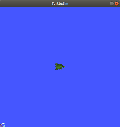
Try exploring the other services offered, or creating more turtles at different locations and moving them around.
Let's move on to actions. As mentioned previously, actions differ from services in a few ways and offer a number of advantages. Actions have the following advantages:
- Actions have a
goal. That is to say you send them a goal, and they attempt to complete it. - Actions can reject goal requests. This prevents them from becoming too busy.
- Actions are asynchronous and can perform tasks "while you wait."
- Actions will provide you with "updates" with information about their progress while you wait.
- Actions are preemptable, meaning you can cancel them if you change your mind.
Just like with services, we'll first figure out how to call the sole action in
our ROS system by using the action list, action show, and action info
commands. Recall, that when we called ros2 action list we got a single
service. Now that we have Larry things have changed. Let's take a look:
$ ros2 action list
/Larry/rotate_absolute
/turtle1/rotate_absolute
Now there are two actions available, one for Larry and one for turtle1.
Let's rotate turtle1 to face Larry. First we'll call action info
using /turtle1/rotate_absolute as the input and see what we get:
$ ros2 action info /turtle1/rotate_absolute
Action: /turtle1/rotate_absolute
Action clients: 0
Action servers: 1
    /turtlesim
Well, that tells us about the client and servers, but it really isn't
helpful for our goal of moving Larry. Why don't we look at the action send_goal help and see if we can
figure out how to use it:
$ ros2 action send_goal --help
usage: ros2 action send_goal [-h] [-f] action_name action_type goal

Send an action goal

positional arguments:
  action_name     Name of the ROS action (e.g. '/fibonacci')
  action_type     Type of the ROS action (e.g.
                  'example_interfaces/action/Fibonacci')
  goal            Goal request values in YAML format (e.g. '{order: 10}')

optional arguments:
  -h, --help      show this help message and exit
  -f, --feedback  Echo feedback messages for the goal
This command needs an action name, an action type, and a goal in YAML. We know the action name, and we know how to write YAML, so all we need is to determine the action type. The best way to get the action type is the same way we published a message.
We see each of our turtles have one service called rotate_absolute.
Let's dig into this action using the info sub command. This command has a -t
flag to list the types of messages.
$ ros2 action info /turtle1/rotate_absolute -t
Action: /turtle1/rotate_absolute
Action clients: 0
Action servers: 1
  /turtlesim [turtlesim/action/RotateAbsolute]
The first line lists the action
name. The second line gives the current number of clients for the
action. The Action servers line gives the total number of action
servers for this action. The last line gives the package and message
type for the action.
We can see here that we need to know the action name, the type, and the values. Now the only problem is figuring out the format of the action type.
Let's understand the RotateAbsolute action message
The ros2 interface show command can be used to find the type of action
message. Let's take a look:
$ ros2 interface show turtlesim/action/RotateAbsolute
# The desired heading in radians
float32 theta #< --- This section is the GOAL
---
# The angular displacement in radians to the starting position
float32 delta #< --- This section is the final result, different from the goal.
---
# The remaining rotation in radians
float32 remaining # < --- This is the current state.
What does this say about rotate absolute?
- There is a float input,
theta, the desired heading. This first section is the actual goal. deltais the angle from the initial heading. This is the value returned when the action completes.remainingis the remaining radians to move. This is the value posted by the action while the action is being done.
With this information we can create our call to the action server. We'll
use the -f flag to make this a bit clearer. Keep an eye on your turtle! It should move, slowly.
$ ros2 action send_goal -f /turtle1/rotate_absolute turtlesim/action/RotateAbsolute {'theta: 1.70'}
Waiting for an action server to become available...
Sending goal:
  theta: 1.7

Feedback:
  remaining: 0.11599969863891602

Goal accepted with ID: 35c40e91590047099ae5bcc3c5151121

Feedback:
 remaining: 0.09999966621398926

Feedback:
 remaining: 0.06799960136413574

Feedback:
 remaining: 0.03599953651428223

Result:
 delta: -0.09600019454956055

Goal finished with status: SUCCEEDED
If everything worked correctly we should see our turtle has rotated.
ROS Parameters
In ROS, parameters are values that are shared between nodes in the system (if you are familiar with the blackboard design pattern in software engineering). Parameters are values that any node can query or write to. Another good analogy would be global constants in normal software programs. Parameters are best used to configure your robot. For example, if you were building an autonomous vehicle and wanted to cap the maximum velocity of the vehicle at 100 km/h, you could create a parameter called "MAX_SPEED" that is visible to all the nodes.
Let's take a look at the param command by running ros2 param --help.
$ ros2 param --help
Various param related sub-commands

Commands:
  delete  Delete parameter
  get     Get parameter
  list    Output a list of available parameters
  set     Set parameter
  Call `ros2 param <command> -h` for more detailed usage.
At a high level, ROS 2's param command has sub commands to get and set a variable,
along with a list functionality, and a delete command. As with most of the
other commands we've worked through, it is instructive to look at list
first. Let's see what the docs say about the list command and then see what
happens when we call the sub command:
$ ros2 param list --help
usage: ros2 param list [-h] [--spin-time SPIN_TIME] [--include-hidden-nodes]
                       [--param-prefixes PARAM_PREFIXES [PARAM_PREFIXES ...]]
                       [node_name]

Output a list of available parameters

positional arguments:
  node_name             Name of the ROS node

optional arguments:
  -h, --help            show this help message and exit
  --spin-time SPIN_TIME
                        Spin time in seconds to wait for discovery (only
                        applies when not using an already running daemon)
  --include-hidden-nodes
                        Consider hidden nodes as well
  --param-prefixes PARAM_PREFIXES [PARAM_PREFIXES ...]
                        Only list parameters with the provided prefixes
$ ros2 param list
/turtlesim:
  background_b
  background_g
  background_r
  use_sim_time
The only argument of note in this sub command is the node_name which allows
you to narrow the scope of param list to only those parameters used by a particular
node. In terms of parameters in the turtlesim node, we see that our call to param list gives us: three background color control params named
background_x and a use_sim_time parameter. To learn all about the param
command why don't we try to change these background color parameters using the
CLI.
The first step in changing the background color is to see what the current color
is. The param get sub command requires both a node name and a parameter
name. In our list above we can see the node name as the top level element with
the forward slash in front of it, namely /turtlesim. The syntax for param get is ros2 param get <node_name> <param>. Let's give it a whirl and see our
current background color values.
$ ros2 param get /turtlesim background_b
Integer value is: 255
$ ros2 param get /turtlesim background_g
Integer value is: 86
$ ros2 param get /turtlesim background_r
Integer value is: 69
On most computers color is represented as a triplet of <R,G,B> values. The color value of <69,86,255> corresponds to a periwinkle blue color. To change the color of the turtlesim we need to first set the parameter value and then reset the turtlesim to make it apply the color changes. We covered the basics of calling a service previously so we won't cover the steps of constructing a service call. Let's try setting our background color's blue component to 128.
$ ros2 param set turtlesim background_b 128
Set parameter successful
$ ros2 service call /reset std_srvs/srv/Empty
requester: making request: std_srvs.srv.Empty_Request()

response:
std_srvs.srv.Empty_Response()
If everything worked correctly your turtle should look like the screen below.
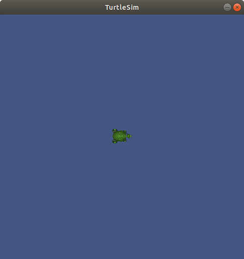
ROS Bags
ROS bags are ROS's tool for recording, and replaying data. ROS bags are like log files that let you store data along with messages. ROS systems can generate a lot of data, so when you bag data you must select which topics you want. Bags are a great tool for testing and debugging your application and a great tool for building robust unit tests.
Let's take a look at the root ROS Bag command by typing ros2 bag --help into
the terminal. If you get an error you might need to install ROS Bag as it is
often in a separate package. On Linux you can run sudo apt install ros-eloquent-ros2bag and it should automatically install the package for you.
$ ros2 bag -h
usage: ros2 bag [-h] Call `ros2 bag <command> -h` for more detailed usage. ...

Various rosbag related sub-commands

Commands:
  info    ros2 bag info
  play    ros2 bag play
  record  ros2 bag record
As you can see there are three sub commands, record, play, and info. With these
commands you can record a bag file, play/replay a file you've recorded, and find information about a bag file.
Let's try recording our first bag file. To do this we'll need three terminals all
running ROS. The first terminal should already have our turtlesim running. If it
isn't running you can restart it with ros2 run turtlesim turtlesim_node. Next
you'll need to start the draw_square demo again to get the default turtle
moving. To do this run ros2 run turtlesim draw_square. Now, in a third
terminal we can bag some data by running the bag command. Let's first look at
the record sub command by running ros2 bag record -h
$ ros2 bag record -h
usage: ros2 bag record [-h] [-a] [-o OUTPUT] [-s STORAGE]
                       [-f SERIALIZATION_FORMAT] [--no-discovery]
                       [-p POLLING_INTERVAL] [-b MAX_BAG_SIZE]
                       [topics [topics ...]]

ros2 bag record

positional arguments:
  topics                topics to be recorded

optional arguments:
  -h, --help            show this help message and exit
  -a, --all             recording all topics, required if no topics are listed
                        explicitly.
  -o OUTPUT, --output OUTPUT
                        destination of the bagfile to create, defaults to a
                        timestamped folder in the current directory
  -s STORAGE, --storage STORAGE
                        storage identifier to be used, defaults to "sqlite3"
  -f SERIALIZATION_FORMAT, --serialization-format SERIALIZATION_FORMAT
                        rmw serialization format in which the messages are
                        saved, defaults to the rmw currently in use
  --no-discovery        disables topic auto discovery during recording: only
                        topics present at startup will be recorded
  -p POLLING_INTERVAL, --polling-interval POLLING_INTERVAL
                        time in ms to wait between querying available topics
                        for recording. It has no effect if --no-discovery is
                        enabled.
  -b MAX_BAG_SIZE, --max-bag-size MAX_BAG_SIZE
                        maximum size in bytes before the bagfile will be
                        split. Default it is zero, recording written in single
                        bagfile and splitting is disabled.
We can see from the help file that the syntax for recording a bag is to simply
give the sub command a list of topics to record. Most of the other arguments are
for more advanced users to help configure how and when data is stored. It is
worth noting that there is a -a, --all command that records all the data. You
can also specify the output bag file with the -o, --output command.
Let's go ahead and run our bag command, and let's bag the pose data on the
/turtle1/pose topic and save it to the file turtle1.bag using the -o
flag. Be aware that the program will continue bagging data until you hit
CTRL-C, so give the command a good 30 seconds to collect data before you kill
it.
$ ros2 bag record /turtle1/pose -o turtle1
[INFO] [rosbag2_storage]: Opened database 'turtle1'.
[INFO] [rosbag2_transport]: Listening for topics...
[INFO] [rosbag2_transport]: Subscribed to topic '/turtle1/pose'
[INFO] [rosbag2_transport]: All requested topics are subscribed. Stopping discovery...
^C[INFO] [rclcpp]: signal_handler(signal_value=2)
Now that we collected our data let's inspect our bag file. You can introspect
any bag file using the ros2 bag info command. This command will list the
messages in the bag, the duration of file, and the number of messages.
$ ros2 bag info turtle1
Files:             turtle1.db3
Bag size:          268.4 KiB
Storage id:        sqlite3
Duration:          68.705s
Start:             May  4 2020 16:10:26.556 (1588633826.556)
End                May  4 2020 16:11:35.262 (1588633895.262)
Messages:          4249
Topic information: Topic: /turtle1/pose | Type: turtlesim/msg/Pose | Count: 4249 | Serialization Format: cdr
Once you have collected a bag file you can replay the file just like a running system. Bags are a great tool for debugging and testing. You can treat a ROS bag like a recording of a running ROS system. When you play a bag file you can use most of the ros2 CLI tools to inspect the recorded topics.
To replay the bag, first use CTRL-C to turn off the
turtlesim_node and the draw_square node. Now in a new terminal replay the bag
file using the following command:
$ ros2 bag play turtle1
[INFO] [rosbag2_storage]: Opened database 'turtle1'.
Nothing should happen visibly, but a lot is happening under the hood.
To see what is happening go to a second terminal. Just like a running robot,
you should be able to list and echo topics:
$ ros2 topic list
/parameter_events
/rosout
/turtle1/pose

$ ros2 bag info turtle1
x: 3.8595714569091797
y: 3.6481313705444336
theta: -1.2895503044128418
linear_velocity: 1.0
angular_velocity: 0.0
---
ROS2 Component Command
ROS2 Daemon Command
ROS2 Doctor Command
With any complex system problems can sometimes arise, and knowing how to describe your
system and what is happening can do a lot to help others help you fix your
problem. ROS 2 has a doctor command that you can use to print a variety of
reports that you can use to help communicate the state of your system to others
trying to provide help. Whether it is one of your co-workers, a vendor, or an
on-line forum, providing detailed and complete information about your ROS system
can go a long way to solving your problem. Let's call --help on the ROS 2
doctor command:
$ ros2 doctor --help
usage: ros2 doctor [-h] [--report | --report-failed] [--include-warnings]

Check ROS setup and other potential issues

optional arguments:
  -h, --help            show this help message and exit
  --report, -r          Print all reports.
  --report-failed, -rf  Print reports of failed checks only.
  --include-warnings, -iw
                        Include warnings as failed checks. Warnings are
                        ignored by default.
As we can see from the help file we have a couple of report options. One option
is to print the full report with -r, or just what failed with -rf. If you're
running ros2 doctor -r you should see a fairly lengthy report generated giving
information about your computer's operating system, your networking
configuration, and your running ROS system. If you ever run into an issue you
should always include this full report.
ROS 2 Interface
As you've already seen, ROS uses standard messages so that different packages and programs, potentially written in different programming languages, can all talk to one another. To make this all work, ROS uses standard messages, and communication protocols built on top of those standard messages. This can make finding type information about a particular message, service, or action difficult. To help developers write both CLI command calls and develop client code, the ROS CLI has the interface command. We've touched on this command briefly in other sections, as it is the go to tool for message type information.
To better understand the interface command let's start by looking at its high
level help command to see what sub commands are available:
$ ros2 interface --help
usage: ros2 interface [-h]
                      Call `ros2 interface <command> -h` for more detailed
                      usage. ...

Show information about ROS interfaces

optional arguments:
  -h, --help            show this help message and exit

Commands:
  list      List all interface types available
  package   Output a list of available interface types within one package
  packages  Output a list of packages that provide interfaces
  proto     Output an interface prototype
  show      Output the interface definition

  Call `ros2 interface <command> -h` for more detailed usage.
The interface command are all geared towards helping you understand
available message types. Let's examine the list sub command in depth. list
will list all of the available messages, services, and actions on your
system. This command has flags that can help you narrow down the scope of your
search. Even a basic ROS installation has a lot of messages, so a tool you
should get familiar with is grep. grep lets you search through some text to
find what you are looking for quickly and easily. You can grep in a case
insensitive manner using the -i flag followed by the text you want to search
for. We can tie this CLI tool to our interface tool by using the UNIX pipe operator |. The example below
shows you how to use the list operation and then how to use it to search:
$ ros2 interface list --only-msgs
Messages:
    action_msgs/msg/GoalInfo
    action_msgs/msg/GoalStatus
	... <DOZENS OF DIFFERENT TYPES> ...
	visualization_msgs/msg/MarkerArray
    visualization_msgs/msg/MenuEntry
$ ros2 interface list --only-msgs | grep -i point
    geometry_msgs/msg/Point
    geometry_msgs/msg/Point32
    geometry_msgs/msg/PointStamped
    map_msgs/msg/PointCloud2Update
    pcl_msgs/msg/PointIndices
    rcl_interfaces/msg/FloatingPointRange
    sensor_msgs/msg/PointCloud
    sensor_msgs/msg/PointCloud2
    sensor_msgs/msg/PointField
    trajectory_msgs/msg/JointTrajectoryPoint
Using grep to search through CLI output is a common tactic used by developers to
find just the specific information they need. The next two sub commands
package and packages can be used to first determine what ROS packages are on
your system, and then to drill down into an individual package to determine what
messages are in that package. Note that
you can use grep just like before to search for your specific interest. The
example below shows you how to first determine if std_msgs is installed and
then to find out what sort of array types it contains:
$ ros2 interface packages
action_msgs
action_tutorials_interfaces
actionlib_msgs
builtin_interfaces
composition_interfaces
diagnostic_msgs
example_interfaces
geometry_msgs
lifecycle_msgs
logging_demo
map_msgs
nav_msgs
pcl_msgs
pendulum_msgs
rcl_interfaces
rosgraph_msgs
rqt_py_common
sensor_msgs
shape_msgs
std_msgs
std_srvs
stereo_msgs
tf2_msgs
trajectory_msgs
turtlesim
unique_identifier_msgs
visualization_msgs
kscottz@kscottz-ratnest:~/Code/ros2multirobotbook/src$ ros2 interface package std_msgs | grep -i array
std_msgs/msg/Int8MultiArray
std_msgs/msg/Int32MultiArray
std_msgs/msg/MultiArrayLayout
std_msgs/msg/UInt64MultiArray
std_msgs/msg/Float32MultiArray
std_msgs/msg/UInt16MultiArray
std_msgs/msg/UInt32MultiArray
std_msgs/msg/Int16MultiArray
std_msgs/msg/ByteMultiArray
std_msgs/msg/Int64MultiArray
std_msgs/msg/Float64MultiArray
std_msgs/msg/UInt8MultiArray
std_msgs/msg/MultiArrayDimension
The next two commands are particularly
helpful and you should remember them as they will make your life much easier. As
we have discussed previously all message publication, service calls, and action
calls in the CLI take in both the message type and data you want to transmit in
YAML format. But what if you don't know the message format, and you don't know a lot about
YAML? The interface show and interface proto commands make this process
easier by respectively telling you first the message type and then the message
format. Recall earlier in the chapter when we called the spawn service on
our turtle simulation. We can use interface show to tell us broadly about the
service and what each of the values mean. We can then use interface proto,
short for prototype, to then generate an empty message that we can fill
out. See the example below:
$ ros2 interface show turtlesim/srv/Spawn
float32 x
float32 y
float32 theta
string name # Optional.  A unique name will be created and returned if this is empty
---
string name
$ ros2 interface proto turtlesim/srv/Spawn
"x: 0.0
y: 0.0
theta: 0.0
name: ''
"
$ ros2 service call /spawn turtlesim/srv/Spawn "{<copy and paste proto here>}"
You can see from the example above how handy these tools can be. It is worth
noting that you need to paste the prototype into a set of quotes and curly
braces for the call to work "{<prototype>}".
ROS 2 Launch
The launch command is used to run ROS launch files. Up until this point we've
been running single ROS programs by hand using the run command, however this
is not how larger ROS systems are generally operated and many robots command
tens if not hundreds of small programs. The ROS launch command is different from
most of the other ROS commands in that it has no sub commands and has a single
function, to start a ROS launch file that executes multiple of programs.
To illustrate this command let's take a look at
its help file.
$ ros2 launch -h
usage: ros2 launch [-h] [-d] [-p | -s] [-a]
                   package_name [launch_file_name]
                   [launch_arguments [launch_arguments ...]]

Run a launch file

positional arguments:
  package_name          Name of the ROS package which contains the launch file
  launch_file_name      Name of the launch file
  launch_arguments      Arguments to the launch file; '<name>:=<value>' (for
                        duplicates, last one wins)

optional arguments:
  -h, --help            show this help message and exit
  -d, --debug           Put the launch system in debug mode, provides more
                        verbose output.
  -p, --print, --print-description
                        Print the launch description to the console without
                        launching it.
  -s, --show-args, --show-arguments
                        Show arguments that may be given to the launch file.
  -a, --show-all-subprocesses-output
                        Show all launched subprocesses' output by overriding
                        their output configuration using the
                        OVERRIDE_LAUNCH_PROCESS_OUTPUT envvar.
Launch files are usually included with a ROS package and are commonly stored in a
launch sub directory. Modern launch files are usually written in Python and end
with the *.launch.py file extension. The launch command has two arguments,
the first one is the package name and then the launch file name. If you are unaware
of the launch files in your package you can use tab completion to list all the
available launch files. Finally, some launch files have arguments that can be
appended to the command. If you are unsure about what a launch file does, or
what arguments it needs, the --print and --show-args commands will tell you
this information. Let's read up on the multisym.launch.py launch file and then
run it following the example below (end the simulation with CTRL-C):
$ ros2 launch turtlesim multisim.launch.py --show-args
Arguments (pass arguments as '<name>:=<value>'):

  No arguments.

$ ros2 launch turtlesim multisim.launch.py --print
<launch.launch_description.LaunchDescription object at 0x7f75aab63828>
├── ExecuteProcess(cmd=[ExecInPkg(pkg='turtlesim', exec='turtlesim_node'), '--ros-args'], cwd=None, env=None, shell=False)
└── ExecuteProcess(cmd=[ExecInPkg(pkg='turtlesim', exec='turtlesim_node'), '--ros-args'], cwd=None, env=None, shell=False)

$ ros2 launch turtlesim multisim.launch.py
[INFO] [launch]: All log files can be found below /home/kscottz/.ros/log/2020-06-24-14-39-03-312667-kscottz-ratnest-20933
[INFO] [launch]: Default logging verbosity is set to INFO
[INFO] [turtlesim_node-1]: process started with pid [20944]
[INFO] [turtlesim_node-2]: process started with pid [20945]
^C[WARNING] [launch]: user interrupted with ctrl-c (SIGINT)
ROS 2 Lifecycle
ROS 2 has a new feature called lifecycle which allows for greater control over
the state of a ROS node. Roughly, this feature allows nodes to have complex
start-up and shut-down procedures that are correctly handed. An example of such
a node would be one that controls a sensor or actuator that needs to perform a
power-on self-test or calibration procedure prior to running. The ROS design
docs
give a great primer on the states and transitions in a lifecycle
node. Let's look at the
lifecycle command to determine what sub commands are available:
$ ros2 lifecycle -h
usage: ros2 lifecycle [-h]
                      Call `ros2 lifecycle <command> -h` for more detailed
                      usage. ...

Various lifecycle related sub-commands

optional arguments:
  -h, --help            show this help message and exit

Commands:
  get    Get lifecycle state for one or more nodes
  list   Output a list of available transitions
  nodes  Output a list of nodes with lifecycle
  set    Trigger lifecycle state transition

  Call `ros2 lifecycle <command> -h` for more detailed usage.
The nodes sub command will list all the lifecycle nodes on a given system.
Once you have listed the nodes, you can list each node's available
transitions using ros2 lifecycle list <nodename>. These transitions are
dictated by the node's current state with some states having more transitions
available than others. If instead of available transitions you wish to query the
current state you can use lifecycle get to return the current state of
your target node. Once you have satisfactorily determined the state of the node
and the available transitions, the lifecycle set command can be used to trigger
the node to transition to a new state. Generally, these CLI commands are used to
diagnose failure modes of systems, or to manually transition a particular
component.
ROS 2 msg (Message)
ROS 2 Eloquent is the last version of ROS to use the msg command. All of the
commands in msg are mirrored in the interface command. These features are
currently deprecated and will be removed in Foxy.
ROS 2 pkg (Package)
The ROS 2 package command is a very useful command to understand what ROS
packages are installed on your system, where they are installed, and the
executables contained within each package. These tools are particularly useful
for understanding an existing robot configuration and finding tools that are
only used on occasion. Let's start by taking a look at the help file for the pkg command:
$ ros2 pkg -h
usage: ros2 pkg [-h] Call `ros2 pkg <command> -h` for more detailed usage. ...

Various package related sub-commands

optional arguments:
  -h, --help            show this help message and exit

Commands:
  create       Create a new ROS2 package
  executables  Output a list of package specific executables
  list         Output a list of available packages
  prefix       Output the prefix path of a package
  xml          Output the XML of the package manifest or a specific tag

  Call `ros2 pkg <command> -h` for more detailed usage.
This command has a variety of sub commands, many of which should look fairly
familiar at this point. The list sub command acts in a manner very similar to
list sub commands we have discussed previously, but this one only lists the
installed system packages. This sub command is often used with grep to help you
find out if a particular package is installed.
Once you have located an installed package you can then have it list the
executables contained by the package using the executables command. This is
much more practical than finding the executables manually. The sub command takes
in a single argument which is the package name. The executables command has a
single optional argument, --full-path, which will output the full path to all
the executable programs. The example below shows how to use these
commands to check the path for all of the turtlesim executables:
$ ros2 pkg list | grep turtle
turtlesim
$ ros2 pkg executables turtlesim --full-path
/opt/ros/eloquent/lib/turtlesim/draw_square
/opt/ros/eloquent/lib/turtlesim/mimic
/opt/ros/eloquent/lib/turtlesim/turtle_teleop_key
/opt/ros/eloquent/lib/turtlesim/turtlesim_node
If you just wanted to know the path to the turtlesim executables you could use
the prefix sub command, which returns the path for a given package's
executables.
Each ROS package contains an XML file that contains metadata for the package,
including information such as the license, maintainer, and its dependencies. ROS
pkg has a handy xml sub command to print these files to the screen, saving you
the hassle of locating and opening the file. You can use grep on the output of
this command to get just the info you need. Below is an example of xml and prefix used to find
the directory of turtlesim, its maintainer, and its license:
$ ros2 pkg prefix turtlesim
/opt/ros/eloquent
$ ros2 pkg xml turtlesim | grep maintainer
  <maintainer email="dthomas@osrfoundation.org">Dirk Thomas</maintainer>
$ ros2 pkg xml turtlesim | grep license
  <license>BSD</license>
kscottz@kscottz-ratnest:~$
The last sub command in the pkg command is create. create is a tool to help
you create a ROS package. We'll use this sub command later in the chapter to
create a new ROS package. The short of it is that you feed the command your
package name and all of the relevant information for your package as optional
arguments.
ROS 2 Security
The ROS API
ROS comprises many software libraries that provide a wide array of functionality useful when building robot applications. The libraries you need will depend on the details of your project. In this section we will introduce two core libraries that you are likely to interact with frequently when developing with ROS:
rclpy: Python client libraryrclcpp: C++ client library
A ROS client library provides the data structures, functions, and syntactic sugar that make it convenient to develop in a particular programming language. Here we will cover just the Python and C++ libraries because they're the most widely used. But you can find ROS client libraries for many other languages, from Ada to JavaScript to Rust, and beyond.
Publishing and Subscribing to Topics in Python
Publishing data with ROS is easy. Here is a complete Python program that publishes string messages:
from time import sleep
import rclpy
from std_msgs.msg import String

rclpy.init()
node = rclpy.create_node('my_publisher')
pub = node.create_publisher(String, 'chatter', 10)
msg = String()
i = 0
while rclpy.ok():
    msg.data = f'Hello World: {i}'
    i += 1
    print(f'Publishing: "{msg.data}"')
    pub.publish(msg)
    sleep(0.5)
Try it out yourself. (Make sure that in every shell used you have
sourced your ROS setup file as we discussed in the previous chapter; e.g., source /opt/ros/foxy/setup.bash.) Copy the code block above into a file, call
it talker.py, then feed it to your Python3 interpreter:
$ python3 talker.py
You should see:
Publishing: "Hello world: 0"
Publishing: "Hello world: 1"
Publishing: "Hello world: 2"
It prints to console, but is the data going anywhere? We can check
our work using the ros2 topic tool that was introduced earlier. In
another shell (leave your talker running), run:
$ ros2 topic echo chatter
You should see the following, though the numbers will vary depending on timing between the two commands:
data: 'Hello world: 13'
---
data: 'Hello world: 14'
---
data: 'Hello world: 15'
So we have a working talker. Now we can add our own listener to use in
place of ros2 topic. Here is a complete Python program that subscribes
to string messages and prints them to console:
import rclpy
from std_msgs.msg import String

def cb(msg):
    print(f'I heard: "{msg.data}"')

rclpy.init()
node = rclpy.create_node('my_subscriber')
sub = node.create_subscription(String, 'chatter', cb, 10)
rclpy.spin(node)
Try it out yourself. Copy the code block above into a file and call it
listener.py. With your talker still running in one shell, start up your
listener in another shell:
$ python3 listener.py
You should see (again, numbers will vary depending on timing):
I heard: "Hello world: 35"
I heard: "Hello world: 36"
I heard: "Hello world: 37"
Digging into the Python Code
Now that we know these programs work, we can dig into their code. Both programs start with the same preamble:
import rclpy
from std_msgs.msg import String
We need to import the rclpy client library, which gives us
much of what we need to write ROS applications in Python. But we also need
to specifically import the ROS message type(s) that we will use. In this
case we are using the simple std_msgs/String message, which contains a
single field called data, of type string. If we wanted to use the
sensor_msgs/Image message, which represents camera images, then we
would write from sensor_msgs.msg import Image.
After the imports, both programs perform common initialization:
rclpy.init()
node = rclpy.create_node('my_node_name')
We initialize the rclpy library and then call into it to create a
Node object, giving it a name. Subsequently we will operate on that
Node object.
In the talker, we use the Node object to create a Publisher object:
pub = node.create_publisher(String, 'chatter', 10)
We declare the type of data we will publish (std_msgs/String), the
name of the topic on which we will publish (chatter), and the maximum
number of outbound messages to locally queue up (10). That last
argument comes into play when we are publishing faster than subscribers
are consuming the data.
The equivalent step in the listener is to create a Subscription
object:
sub = node.create_subscription(String, 'chatter', cb, 10)
The type (String) and topic name (chatter) arguments have the same meaning
as the create_publisher() call, and the final argument (10) is
setting an analogous maximum queue size for inbound messages. The key
difference is the cb argument, which refers to this callback
function that we also defined in the listener:
def cb(msg):
    print(f'I heard: "{msg.data}"')
That function will be called whenever the listener receives a message, and the received message will be passed in as an argument. In this case we simply print the content to console.
With the callback defined and the Subscription created, the rest of
the listener is one line:
rclpy.spin(node)
This call hands control over to rclpy to wait for new messages to
arrive (and more generally for events to occur) and invoke our callback.
Back in the talker, we create a simple loop to use our Publisher:
msg = String()
i = 0
while rclpy.ok():
    msg.data = f'Hello World: {i}'
    i += 1
    print(f'Publishing: "{msg.data}"')
    pub.publish(msg)
    sleep(0.5)
These steps are clear enough: we create a message object and then on each iteration of the loop, we update the message content and publish it, sleeping briefly between iterations.
Publishing and Subscribing to Topics in C++
Now we will write the same talker and listener pair, this time in C++.
Here is a complete C++ program that publishes string messages:
#include <unistd.h>
#include <iostream>
#include "rclcpp/rclcpp.hpp"
#include "std_msgs/msg/string.hpp"

int main(int argc, char * argv[])
{
  rclcpp::init(argc, argv);
  auto node = rclcpp::Node::make_shared("minimal_publisher");
  auto pub = node->create_publisher<std_msgs::msg::String>("chatter", 10);
  std_msgs::msg::String message;
  auto i = 0;
  while (rclcpp::ok()) {
    message.data = "Hello world: " + std::to_string(i++);
    std::cout << "Publishing: " << message.data << std::endl;
    pub->publish(message);
    usleep(500000);
  }
  return 0;
}
Of course, as for all C++, we need to compile this program. Managing the compilation arguments for C++ is cumbersome, so we use CMake to help. Here is the complete CMake code that allows us to build the talker example:
cmake_minimum_required(VERSION 3.5)
project(talker_listener)

find_package(rclcpp REQUIRED)
find_package(std_msgs REQUIRED)

add_executable(talker talker.cpp)
target_include_directories(talker PRIVATE ${rclcpp_INCLUDE_DIRS} ${std_msgs_INCLUDE_DIRS})
target_link_libraries(talker ${rclcpp_LIBRARIES} ${std_msgs_LIBRARIES})
Try it out yourself. Copy the C++ code into a file called talker.cpp
and the CMake code into a file called CMakeLists.txt. Have them
side-by-side in a directory and then invoke cmake followed by make:
$ cmake .
$ make
You should end up with a compiled executable called talker. Run it:
$ ./talker
You should see:
Publishing: "Hello world: 0"
Publishing: "Hello world: 1"
Publishing: "Hello world: 2"
Keep the talker running and another shell try ros2 topic to listen
in:
$ ros2 topic echo chatter
You should see (numbers will vary depending on timing between the two commands):
data: 'Hello world: 13'
---
data: 'Hello world: 14'
---
data: 'Hello world: 15'
Now we can write our own listener to use in place of ros2 topic. Here
is a complete C++ program that subscribes to string messages and prints
them to console:
#include "rclcpp/rclcpp.hpp"
#include "std_msgs/msg/string.hpp"

void cb(const std_msgs::msg::String::SharedPtr msg)
{
  std::cout << "I heard: " << msg->data << std::endl;
}

int main(int argc, char * argv[])
{
  rclcpp::init(argc, argv);
  auto node = rclcpp::Node::make_shared("my_subscriber");
  auto sub = node->create_subscription<std_msgs::msg::String>("chatter", 10, cb);
  rclcpp::spin(node);
  return 0;
}
Copy the code block into a file called talker.cpp. To arrange for it
to be compiled, we also need to add some corresponding CMake code to the
bottom of our CMakeLists.txt file from earlier:
add_executable(listener listener.cpp)
target_include_directories(listener PRIVATE ${rclcpp_INCLUDE_DIRS} ${std_msgs_INCLUDE_DIRS})
target_link_libraries(listener ${rclcpp_LIBRARIES} ${std_msgs_LIBRARIES})
Configure and build again:
$ cmake .
$ make
Now you should have also have a listener executable. With your talker
still running in one shell, start up your listener in another shell:
$ ./listener
You should see (again, numbers will vary depending on timing):
I heard: "Hello world: 35"
I heard: "Hello world: 36"
I heard: "Hello world: 37"
Digging into the C++ Code
Now that we know these programs work, we can dig into their code. Both programs start with the same preamble:
#include "rclcpp/rclcpp.hpp"
#include "std_msgs/msg/string.hpp"
We always need to include the rclcpp client library, which gives us
much of what we need to write ROS applications in C++. But we also need to
specifically import the ROS message type(s) that we will use. In this
case we are using the simple std_msgs/String message, which contains a
single field called data, of type string. If we wanted to use the
sensor_msgs/Image message, which represents camera images, then we
would #include "sensor_msgs/msg/image.hpp".
After the imports, both programs perform common initialization:
  rclcpp::init(argc, argv);
  auto node = rclcpp::Node::make_shared("my_node_name");
We initialize the rclcpp library and then call into it to create a
Node object, giving it a name. Subsequently we will operate on that
Node object.
In the talker, we use the Node object to create a Publisher object:
auto pub = node->create_publisher<std_msgs::msg::String>("chatter", 10);
We declare via template the type of data we will publish (std_msgs/String), the
name of the topic on which we will publish (chatter), and the maximum
number of outbound messages to locally queue up (10). That last
argument comes into play when we are publishing faster than subscribers
are consuming the data.
The equivalent step in the listener is to create a Subscription
object:
auto sub = node->create_subscription<std_msgs::msg::String>("chatter", 10, cb);
The type (String) and topic name (chatter) arguments have the same meaning
as for the create_publisher() call, and the numerical argument (10) is
setting an analogous maximum queue size for inbound messages. The key
difference is the cb argument, which refers to this callback
function that we also defined in the listener:
void cb(const std_msgs::msg::String::SharedPtr msg)
{
  std::cout << "I heard: " << msg->data << std::endl;
}
That function will be called whenever the listener receives a message, and the received message will be passed in as an argument. In this case we simply print the content to console.
With the callback defined and the Subscription created, the rest of
the listener is one line:
rclcpp::spin(node);
This call hands control over to rclcpp to wait for new messages to
arrive (and more generally for events to occur) and invoke our callback.
Back in the talker, we create a simple loop to use our Publisher:
  std_msgs::msg::String message;
  auto i = 0;
  while (rclcpp::ok()) {
    message.data = "Hello world: " + std::to_string(i++);
    std::cout << "Publishing: " << message.data << std::endl;
    pub->publish(message);
    usleep(500000);
  }
In these steps we create a message object, and then on each iteration of the loop we update the message content and publish it, sleeping briefly between iterations.
Where to Go From Here
That was a very brief introduction and we only covered topics, not services, actions, parameters, or the many other facets of ROS. Luckily, the online ROS tutorials are an excellent resource for learning about the rest of ROS. We specifically recommend the Beginner: Client Libraries collection as a natural next step after reading this chapter.
Regarding the Shortcuts
In this section we have presented the simplest, shortest example ROS programs that we could come up with. Such programs are easy to understand and learn from, as they do not have unnecessary structure or decoration. But in exchange such programs are not easily extensible, composable, or maintainable.
The techniques that we used in the example code in this section are useful for prototyping and experimentation (an important aspect of any good robotics project!), but we do not recommend them for serious work. As you go through the ROS tutorials and start reading existing ROS code, you will learn about a number of concepts, patterns, and conventions, such as:
- organizing your code into packages
- organizing your packages into a workspace
- managing dependencies among packages
- using the
colcontool to build code in multiple packages in dependency order - using the
amentmodule in yourCMakeLists.txtfiles - structuring your code to allow run-time control of how nodes maps to processes
- using the client libraries' console-logging routines for output to screen and elsewhere
These techniques will serve you well when you start building your own ROS applications, especially when you want to share your code with others, whether on your team or out in the world.
Traffic Editor
This section describes the traffic-editor GUI and simulation tools.
Introduction and Objectives
Traffic management of heterogeneous robot fleets is non-trivial. One of the challenges with coordinated management arises from varying semantics in information models used across fleets. Representations of waypoints, lanes, charging/docking stations, restricted zones, infrastructure systems such as doors & lifts, among others, are subject to vendor's discretion. However, standardized conventions that convey the capabilities and intentions of fleets in a shared facility are quintessential for planning. Multi-agent participants in other modes of transportation such as roadways collectively adhere to a set of rules and conventions which minimize chaos. More importantly, they allow for a new participant to readily integrate into the system by following the prescribed rules. Existing agents can accommodate the new participant as its behavior is apparent.
Traffic conventions for multi-robot systems do not exist.
The objective of the traffic_editor is to fill this gap by expressing the
intentions of various fleets in a standardized, vendor neutral manner through a
graphical interface. Collated traffic information from different fleets can then
be exported for planning and control. A secondary objective and benefit of the
traffic_editor is to facilitate generation of 3D simulation worlds which
accurately reflect physical environments.
Overview
The traffic_editor repository is home to the traffic_editor GUI and tools to auto-generate simulation worlds from GUI output.
The GUI is an easy-to-use interface which can create and annotate 2D floor plans with robot traffic along with building infrastructure information.
Often times, there are existing floor plans of the environment, such as architectural drawings, which simplify the task and provide a "reference" coordinate system for vendor-specific maps.
For such cases, traffic-editor can import these types of "backgroud images" to serve as a canvas upon which to draw the intended robot traffic maps, and to make it easy to trace the important wall segments required for simulation.
The traffic_editor GUI projects are stored as yaml files with .building.yaml file extensions.
Although the typical workflow uses the GUI and does not require hand-editing the yaml files directly, we have used a yaml file format to make it easy to parse using custom scripting if needed.
Each .building.yaml file includes several attributes for each level in the site as annotated by the user.
An empty .building.yaml file appears below.
The GUI tries to make it easy to add and update content to these file.
levels:
  L1:
    doors:
      - []
    drawing:
      filename:
    fiducials:
    elevation: 0
    flattened_x_offset: 0
    flattened_y_offset: 0
    floors:
      - parameters: {}
        vertices: []
    lanes:
      - []
    layers:
      {}
    measurements:
      - []
    models:
      -{}
    vertices:
      {}
    walls:
      {}
lifts:
  {}
name: building
GUI Layout
The layout of the traffic_editor includes a Toolbar, a Working Area and a Sidebar as seen in the figure below:
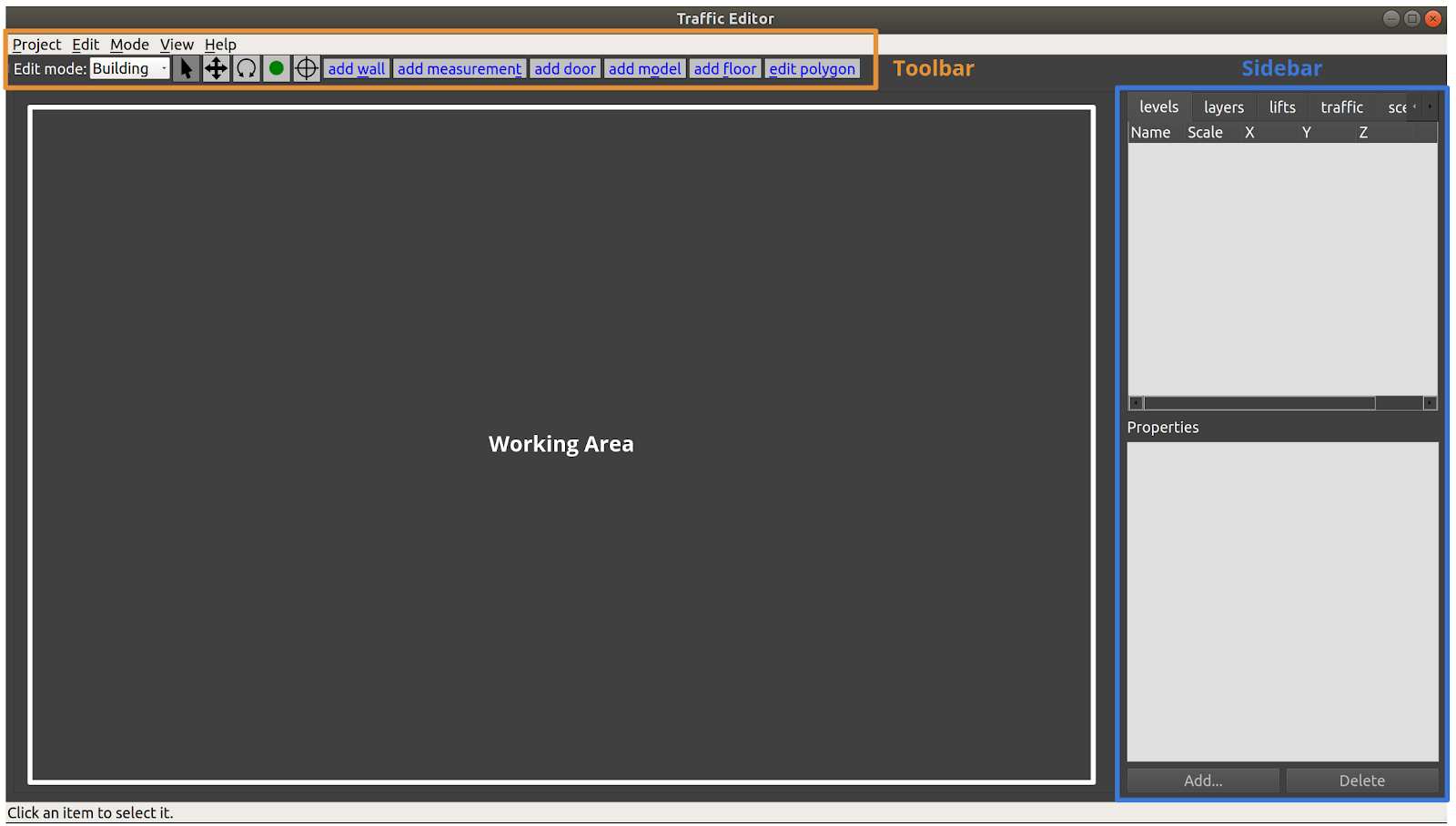
The toolbar contains a variety of tools to support actions such as setting the scale of the drawing, aligning levels for multi-level scenarios, adding virtual models to simulated environments, adding robot traffic lanes, simulated flooring, and so on.
As usual in a modern GUI, the top Toolbar contains a variety of tools to interact with items in the main Working Area. This document will introduce and explain the tools as an example project is created. However, the first three tools in the toolbar are commonly found in 2D drawing tools, and should behave as expected:
| Icon | Name | Shortkey | Function |
|---|---|---|---|
| Select | Esc | Select an entity in the Working Area | |
| Move | m | Move an entity in the Working Area | |
| Rotate | r | Rotate an entity in the Working Area |
The Working Area is where the levels, along with their annotations, are rendered.
The user is able to zoom via the mouse scroll wheel, and pan the view by pressing the scroll wheel and moving the mouse cursor.
The Sidebar on the right side of the window contains multiple tabs with various functionalities:
- levels: to add a new level to the building. This can be done from scratch or by importing a floor plan image file.
- layers: to overlap other images such as lidar maps over the level
- lifts: to configure and add lifts to the building
- traffic: to select which "navigation graph" is currently being edited, and toggle which graph(s) are being rendered.
Annotation Guide
This section walks through the process of annotating facilities while highlighting the capabilities of the traffic_editor GUI.
To create a new traffic editor Building file, launch the traffic editor from a terminal window (first sourcing the workspace if traffic-editor is built from source).
Then, click Building -> New... and choose a location and filename for your .building.yaml file.
Adding a level
A new level in the building can be added by clicking the Add button in the levels tab of the Sidebar.
The operation will open a dialog box where the name, elevation (in meters) and path to a 2D drawing file (.png) can be specified.
In most use cases, the floor plan for the level is used as the drawing.
If unspecified, the user may explicitly enter dimensions of the level in the fields provided.
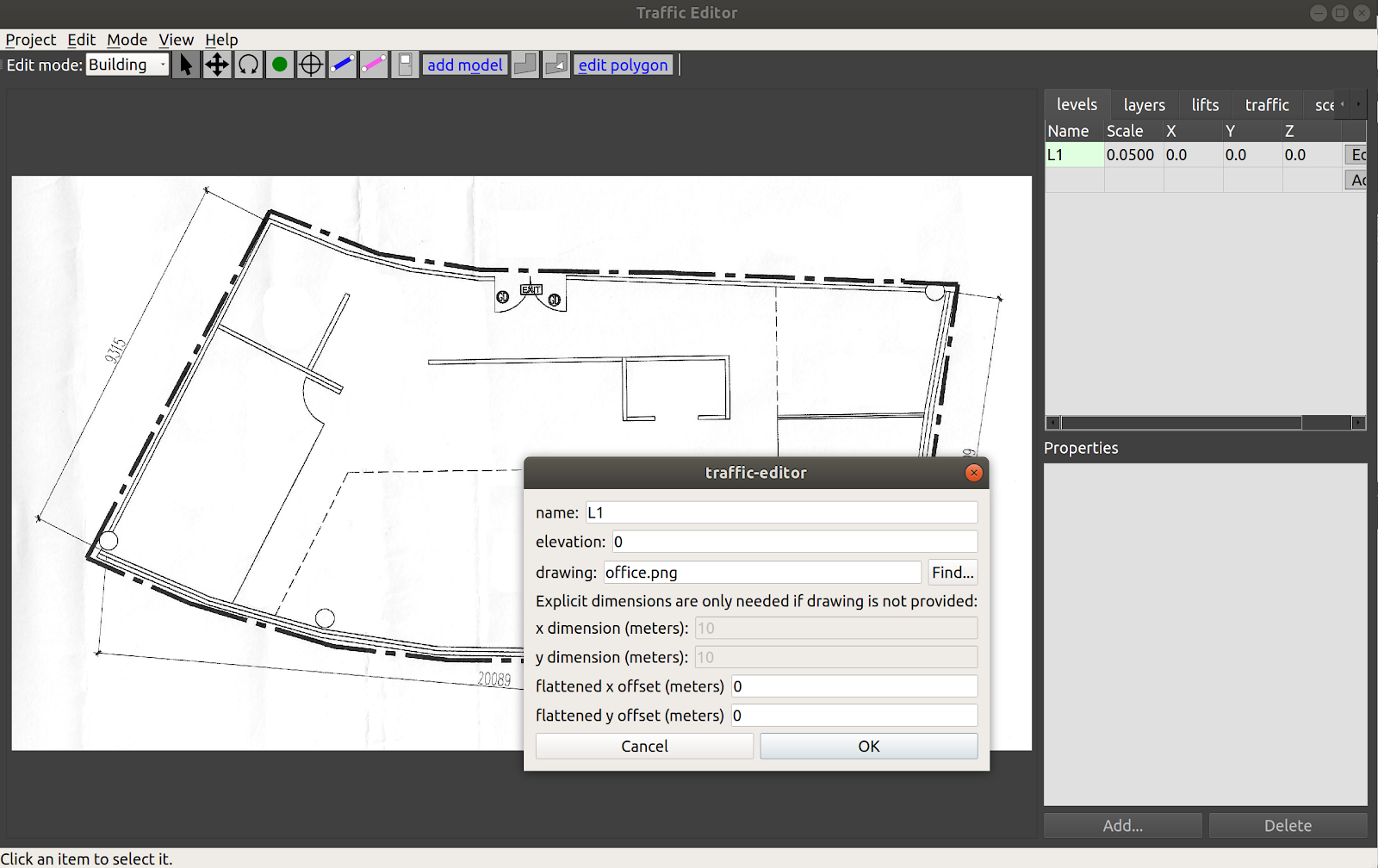
In the figure above, a new level L1 at 0m elevation and a floor plan have been added as reflected in the levels tab.
A default scale 1px = 5cm is applied.
The actual scale can be set by adding a measurement.
Any offsets applied to align levels will be reflected in the X and Y columns.
Saving the project will update the tutorial.building.yaml files as seen below:
levels:
  L1:
    drawing:
      filename: office.png
    elevation: 0
    flattened_x_offset: 0
    flattened_y_offset: 0
    layers:
      {}
lifts:
  {}
name: building
Adding a vertex
| Icon | Shortkey |
|---|---|
v |
A vertex is a fundamental component of multiple annotations.
Walls, measurements, doors, floor polygons and traffic lanes are created from two or more vertices.
To create a vertex, click on the vertex icon in the Toolbar and then click anywhere on the canvas.
The default attributes of a vertex are its coordinates along with an empty name field.
Additional attributes may be added by first selecting the vertex (which will turn it red), and then clicking the Add button in the figure.
Short descriptions of these are presented below:
- is_holding_point: if true and if the waypoint is part of a traffic lane,
the
rmf_fleet_adapterwill treat this as a holding point during path planning, i.e., the robot is allowed to wait at this waypoint for an indefinite period of time. - is_parking_spot: robot's parking spot. Definition
- is_passthrough_point: waypoint which the robot shouldnt stop. Definition
- is_charger: if true and if the waypoint is part of a traffic lane, the
rmf_fleet_adapterwill treat this as a charging station. - is_cleaning_zone indicate if current waypoint is a cleaning zone, specifically for
CleanTask. - dock_name: if specified and if the waypoint is part of a traffic lane, the
rmf_fleet_adapterwill issue anrmf_fleet_msgs::ModeRequestmessage withMODE_DOCKINGandtask_idequal to the specified name to the robot as it approaches this waypoint. This is used when the robot is executing their custom docking sequence (or custom travel path). - spawn_robot_type: the name of the robot model to spawn at this waypoint in simulation. The value must match the model's folder name in the assets repository. More details on the robot model and plugin required for simulation can be found in Simulation
- spawn_robot_name: a unique identifier for the robot spawned at this
waypoint. The
rmf_fleet_msgs::RobotStatemessage published by this robot will havenamefield equal to this value. - pickup_dispenser name of the dispenser workcell for
DeliveryTask, typically is the name of the model. See the [Workcell section] (https://osrf.github.io/ros2multirobotbook/simulation.html#workcells) of the Simulation Chapter for more details. - dropoff_ingestor name of the ingestor workcell for
DeliveryTask, typically is the name of the model. See the [Workcell section] (https://osrf.github.io/ros2multirobotbook/simulation.html#workcells) of the Simulation Chapter for more details. - human_goal_set_name The
goal_sets.set_areaname, used by crowd simulation. For more info aboutcrowd_sim, please see the [Crowdsim section] (https://osrf.github.io/ros2multirobotbook/simulation.html#crowdsim) of the Simulation Chapter for more details.
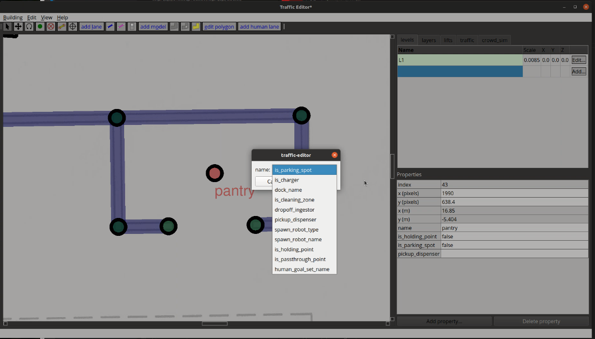
Each vertex is stored in the tutorial.building.yaml file as a list of x-coordinate, y-coordinate, elevation, vertex_name and a set of additional parameters.
  vertices:
    - [1364.76, 1336.717, 0, magni1_charger, {is_charger: [4, true], is_parking_spot: [4, true], spawn_robot_name: [1, magni1], spawn_robot_type: [1, Magni]}]
Adding a measurement
| Icon |
|---|
Adding a measurement sets the scale of the imported 2D drawing, which is essential for planning and simulation accuracy. Scalebars or reference dimensions in the floor plan aid with the process. Often, you can draw the measurement line directly on top of a reference scale bar in a drawing. With the editor in Building mode, select the Add Measurement tool and click on two points with known dimensions. A pink line is rendered on the map with two vertices at its ends at the selected points.
Note: A measurement line may be drawn by clicking on existing vertices. In this scenario, no additional vertices are created at its ends.
Selecting the line populates various parameters in the Properties window of the Sidebar.
Setting the distance parameter to the physical distance between the points (in meters) will then update the Scale for the level.
Currently, you must save the project and restart traffic-editor to see the changes reflected (todo: fix this...).
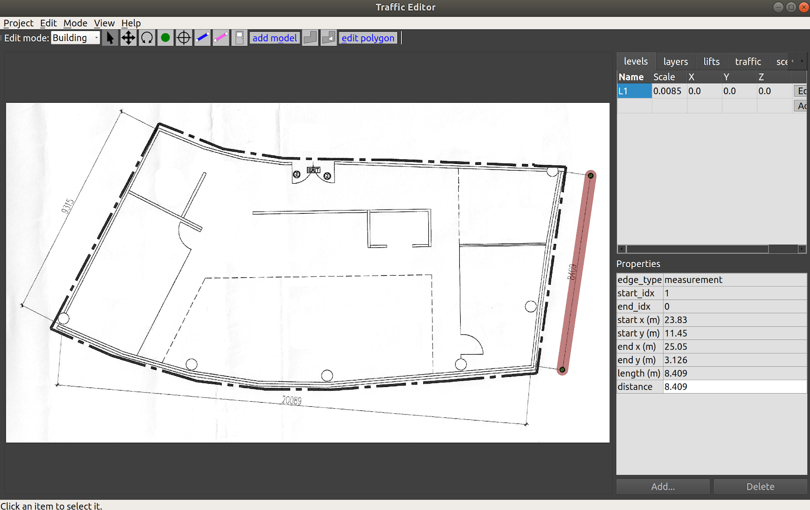
The above process adds two vertices and a measurement field to the tutorial.building.yaml file as seen below.
For the measurement field, the first two elements represent the indices of vertices representing the ends of
the line.
The distance value is stored in a sub-list of parameters.
levels:
  L1:
    drawing:
      filename: office.png
    elevation: 0
    flattened_x_offset: 0
    flattened_y_offset: 0
    layers:
      {}
    measurements:
      - [1, 0, {distance: [3, 8.409]}]
    vertices:
      - [2951.728, 368.353, 0, ""]
      - [2808.142, 1348.9, 0, ""]

lifts:
  {}
name: building
Adding a wall
| Icon | Shortkey |
|---|---|
w |
To annotate walls in the map, select the Add Wall icon from the Toolbar and click on consecutive vertices that represent the corners of the wall.
The process of adding wall segments is continuous, and can be exited by pressing the Esc key.
Blue lines between vertices are rendered on the map which represent the drawn walls.
If the corner vertices are not present, they will automatically be created when using this tool.
Meshes of the annotated walls are automatically generated during 3D world generation using building_map_generator.
By default, the walls are of thickness of 10cm and height 2.5m.
The wall_height and wall_thickness attributes may be
modified in the source code.
Wall texture options are available here in the source code.
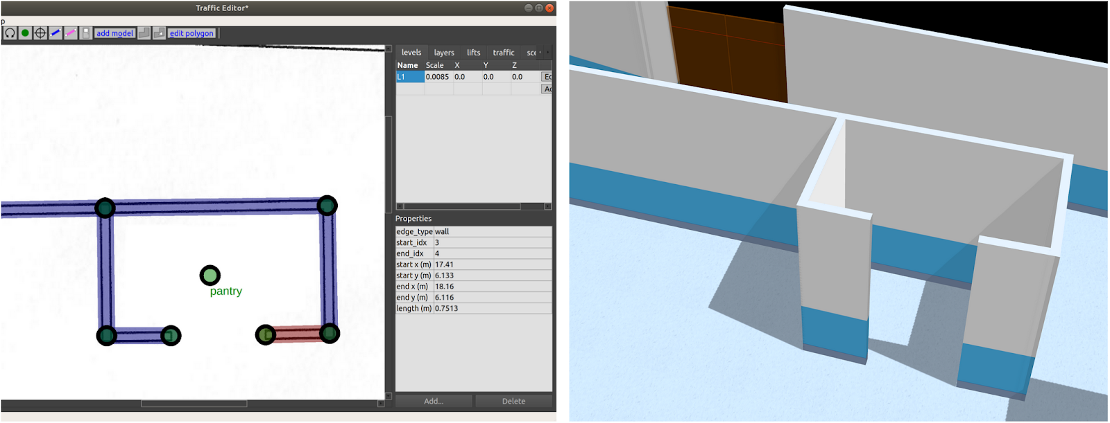
Walls are stored in the tutorial.building.yaml file as a list with indices of start and end vertices of the wall segment along with an empty parameter set.
    walls:
      - [3, 4, {}]
      - [4, 5, {}]
      - [5, 6, {}]
      - [6, 7, {}]
      - [6, 8, {}]
      - [8, 9, {}]
Adding a floor
| Icon |
|---|
Flooring is essential for simulations as it provides a ground plane for the robots to travel over.
Floors are annotated using the Add floor polygon tool from the Main Toolbar in Building edit mode.
To define a floor, select consecutive vertices to create a polygon that accurately represents the flooring area as seen below.
These vertices will need to be added manually prior to this step.
Once created, save the project and reload.
Selecting the defined floor highlights its texture attributes. Similarly, default list of available textures is available in the source code.
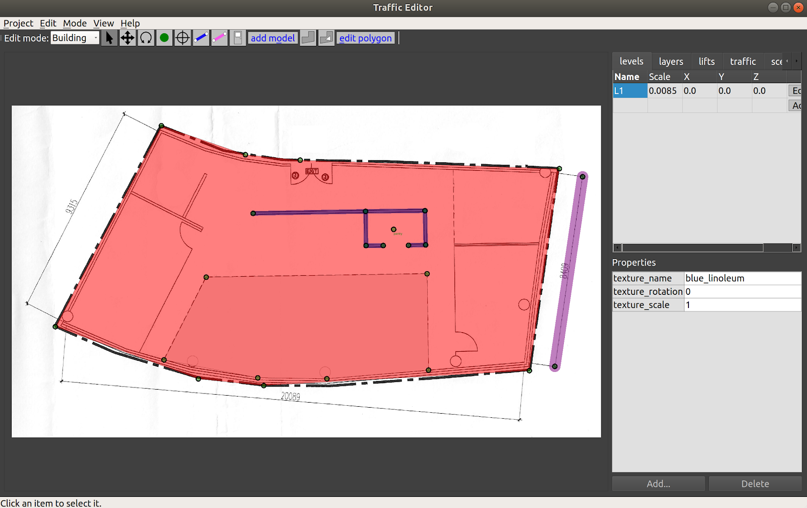
Certain scenarios may call for floors with cavities, for example, to represent elevator shafts. The Add hole polygon tool may be used for this purpose. Additionally, the shape of a drawn polygon (floor or hole) may be modified using the Edit polygon tool. Clicking on the tool after selecting an existing polygon enables the user to modify vertices of the polygon.
Each polygon is stored in the tutorial.building.yaml file in the format below:
    floors:
      - parameters: {texture_name: [1, blue_linoleum], texture_rotation: [3, 0], texture_scale: [3, 1]}
        vertices: [11, 10, 14, 15, 13, 12]
Adding a door
| Icon |
|---|
A door between two vertices can be added in Building edit mode by selecting the Add door tool from the Main Toolbar, and clicking on vertices representing the ends of the door.
Selecting an annotated door highlights its properties as seen in the figure below.
Presently, four door types are supported: "hinged", "double_hinged", "sliding" and "double_sliding".
The motion_degrees parameter specifies the range of motion in the case of hinged doors while the motion_direction dictates the direction of swing.
In order for the door to work in simulation, a name must be given to the door.
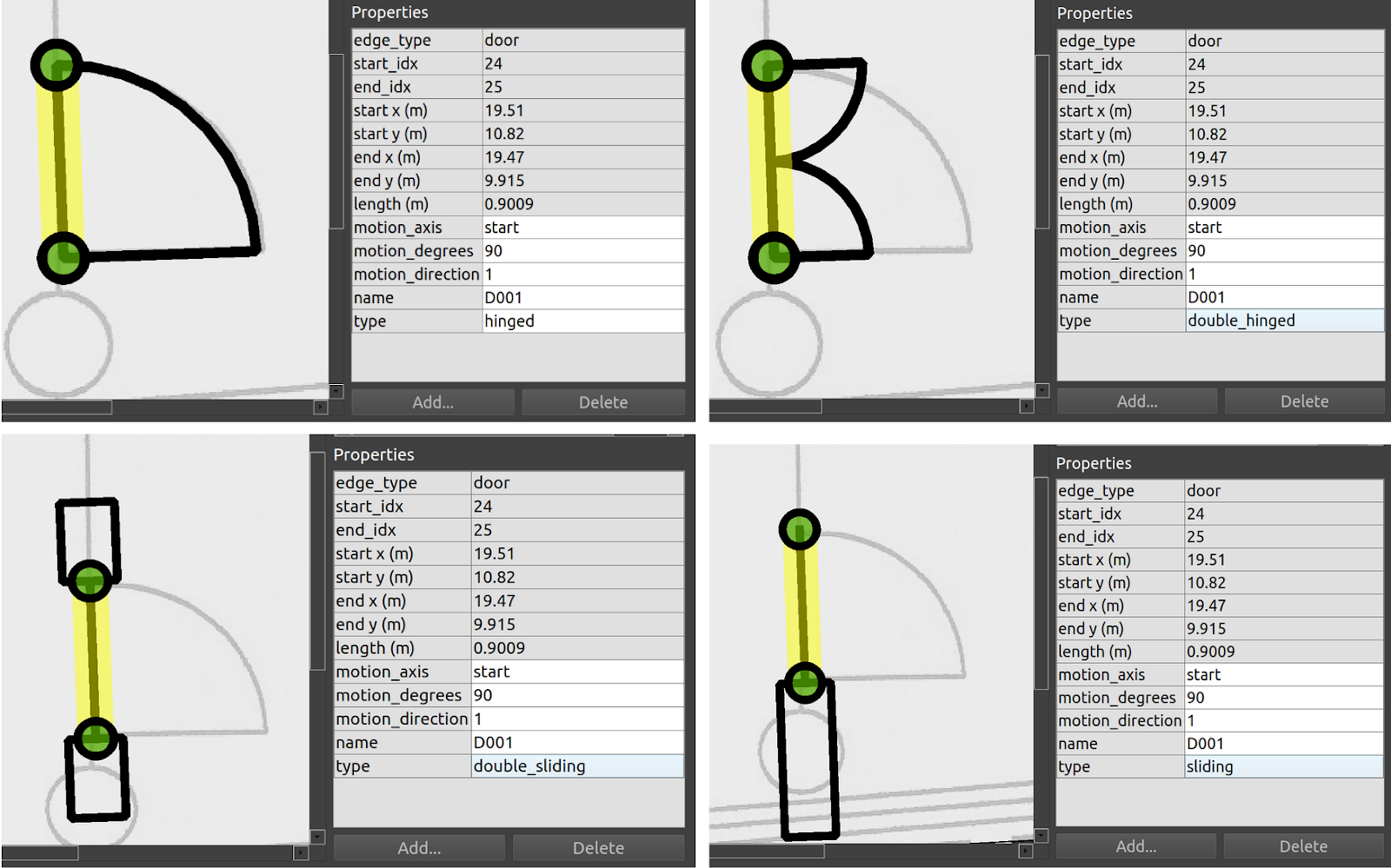
Doors are stored in the tutorial.building.yaml file as a list with indices of start and end vertices along with the set of parameters that describes the door.
 doors:
      - [24, 25, {motion_axis: [1, start], motion_degrees: [3, 90], motion_direction: [2, 1], name: [1, D001], type: [1, double_sliding]}]
Adding a traffic lane
One of the most important tools in the traffic_editor GUI is the Add lane tool.
The allowable motions of each fleet operating in the facility is conveyed through its respective Graph which consists of waypoints and connecting lanes.
In this approach, we assume that robots travel along effectively straight-line paths between waypoints.
While this may be perceived as an oversimplification of paths taken by robots that are capable of autonomous navigation, in practice the assumption holds fairly well given that these robots mostly travel along corridors or hallways and seldom in unconstrained open spaces.
For example, even in theoretically unconstrained spaces like building lobbies or shopping-mall atriums, it is likely that the site operator would prefer for the robots to operate in a "traffic lane" on the edge of the space, in order to not impede typical human traffic flows.
The traffic tab in the Sidebar has a default of nine Graphs for nine different fleets. To annotate lanes for a graph, say Graph 0, select the Graph from the traffic tab and click the Add lane tool.
Lanes for this graph can be drawn by clicking vertices to be connected.
If a vertex is not present, it will automatically be added. Properties may be assigned to each vertex as described in the preceding section.
To issue tasks to waypoints that require the robot to terminate at any waypoint, a name must be assigned to the waypoint.
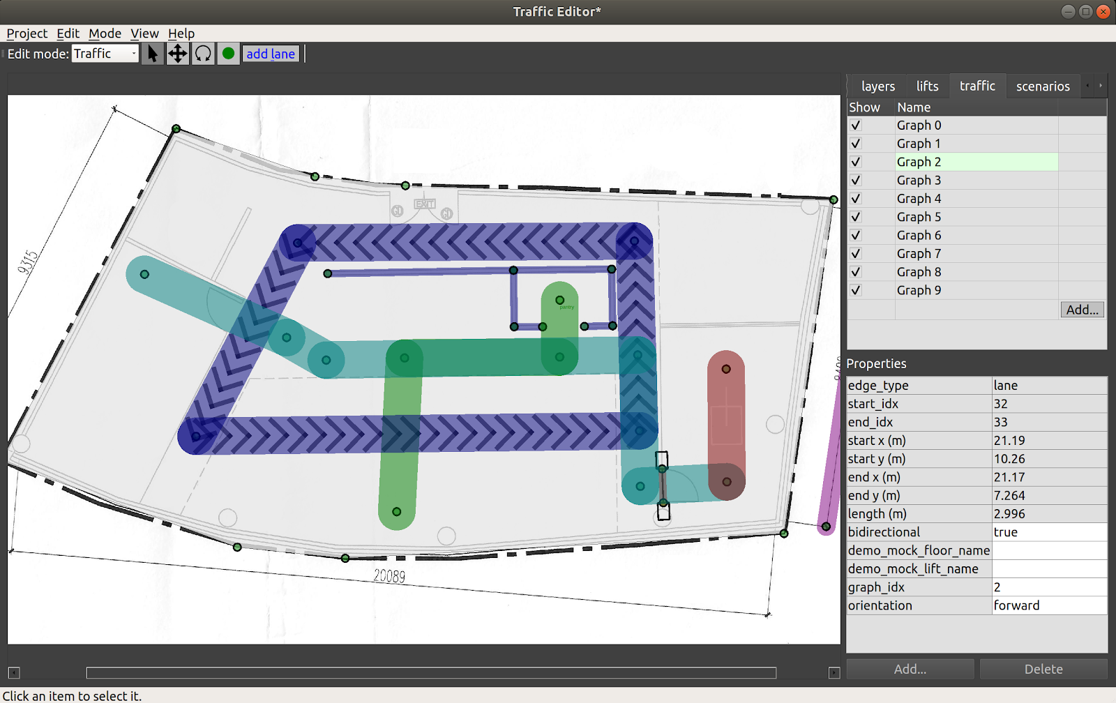
Each Graph has a unique color for its lanes, and their visibility may be toggled using the checkbox in the traffic tab.
A lane that is defined between two waypoints may be configured with these additional properties:
- bidirectional: if
true, thermf_fleet_adapterwill plan routes for its robot assuming the lanes can be traversed in both directions. Lanes that are not bidirectional have arrows indicating their directionality (indigo lanes in figure above). A handy shortcut is that when a lane segment is selected, you can press thebkey to toggle between unidirectional and bidirectional motion along that lane. - graph_idx: the Graph number a lane corresponds to
- orientation: constrain the lane to make the robot travel in
forwardorbackwardorientation. This can be useful for the final lane segment approaching a docking point or charger, for example.
While lifts that move between levels are now supported in the traffic_editor, the demo_mock_floor_name and demo_mock_lift_name properties were originally engineered to showcase shared lift access in a single floor demonstration environment with a "mock" lift that receives lift commands and transmits lift states but does not actually move between any different floors in a building.
However, as there may be interest in such functionality for testing single-floor hardware setups that seek to emulate multi-floor scenarios, these properties were retained.
- demo_mock_floor_name: name of the floor that the robot is on while traversing the lane
- demo_mock_lift_name: name of the lift that is being entered or exited while the robot traverses the lane
To further explain these properties, consider this representation of a navigation graph where numbers are waypoints and letters are lanes:
1 <---a---> 2 <---b---> 3

Waypoint 1 is on floor L1
Waypoint 2 is inside the "lift" named LIFT001
Waypoint 3 is on floor L3
The properties of edge "a" are:
    bidirectional: true
    demo_mock_floor_name: L1
    demo_mock_lift_name: LIFT001
The properties of edge "b" are:
    bidirectional: true
    demo_mock_floor_name: L3
    demo_mock_lift_name: LIFT001
If the robot is to travel from waypoint 1 to waypoint 3, the rmf_fleet_adapter will request for the "mock lift" to arrive at L1 when the robot approaches waypoint 1.
With confirmation of the "lift" at L1 and its doors in "open" state, the robot will be instructed to move into the "lift" to waypoint 2.
Once the "lift" indicates that it has reached L3, the robot will exit along lane b toward waypoint 3.
Note: when annotating graphs, it is highly recommended to follow an ascending sequence of graph indices without skipping intermediate numbers. Drawn lanes can only be interacted with if their associated Graph is first selected in the traffic tab.
The annotated Graphs are eventually exported as navigation graphs using the building_map_generator which are then used by respective rmf_fleet_adapters for path planning.
Lanes are stored in the following format in tutorial.building.yaml.
The data structure is a list with the first two elements representing the indices of the two vertices of the lane and a set of parameters with configured properties.
    lanes:
      - [32, 33, {bidirectional: [4, true], demo_mock_floor_name: [1, ""], demo_mock_lift_name: [1, ""], graph_idx: [2, 2], orientation: [1, forward]}]
Deriving coordinate-space transforms
Coordinate spaces are confusing!
For historical reasons, the GUI internally creates traffic maps by annotating images, so the "raw" annotations are actually encoded in pixel coordinates of the "base" floorplan image, in pixel coordinates, with +X=right and +Y=down, with the origin in the upper-left of the base floorplan image.
However, during the building map generation step, the vertical axis is flipped to end up in a Cartesian plane, so the vast majority of RMF (that is, everything downstream of traffic-editor and the building map generators) uses a "normal" Cartesian coordinate system. (As an aside -- the next version of traffic-editor is intended to be more flexible in this respect, and will default to a normal Cartesian coordinate system (not an image-based coordinate system), or even global coordinates (lat/lon). Although preliminary work is underway, there is not a hard schedule for this next-gen editor at time of writing, so the rest of this chapter will describe the existing traffic-editor.)
Although traffic-editor currently uses the upper-left corner of the base floorplan image as the reference frame, maps generated by robots likely will have their origin elsewhere, and will likely be oriented and scaled differently.
It is critical to derive the correct transform between coordinate frames in traffic_editor maps and robot maps as
rmf_fleet_adapters expect all robots to publish their locations in the RMF coordinate system while the rmf_fleet_adapters also issue path requests in the same frame.
To derive such transforms, the traffic_editor GUI allows users to overlay robot maps on a floor plan and apply scale, translation and rotation transformations such that the two maps align correctly.
The user can then apply the same transformations to convert between robot map and RMF coordinates when programming interfaces for their robot.
The robot map can be imported by clicking the Add button from the layers tab in the Sidebar.
A dialog box will then prompt the user to upload the robot map image.
The same box contains fields for setting the scale for the image along with applying translations and rotation.
Through visual feedback, the user can determine appropriate values for these fields.
As seen in the image below, importing the robot-generated map into the GUI has it located and oriented
differently than the floor plan.
With the right transformation values, the two maps can be made to overlap.
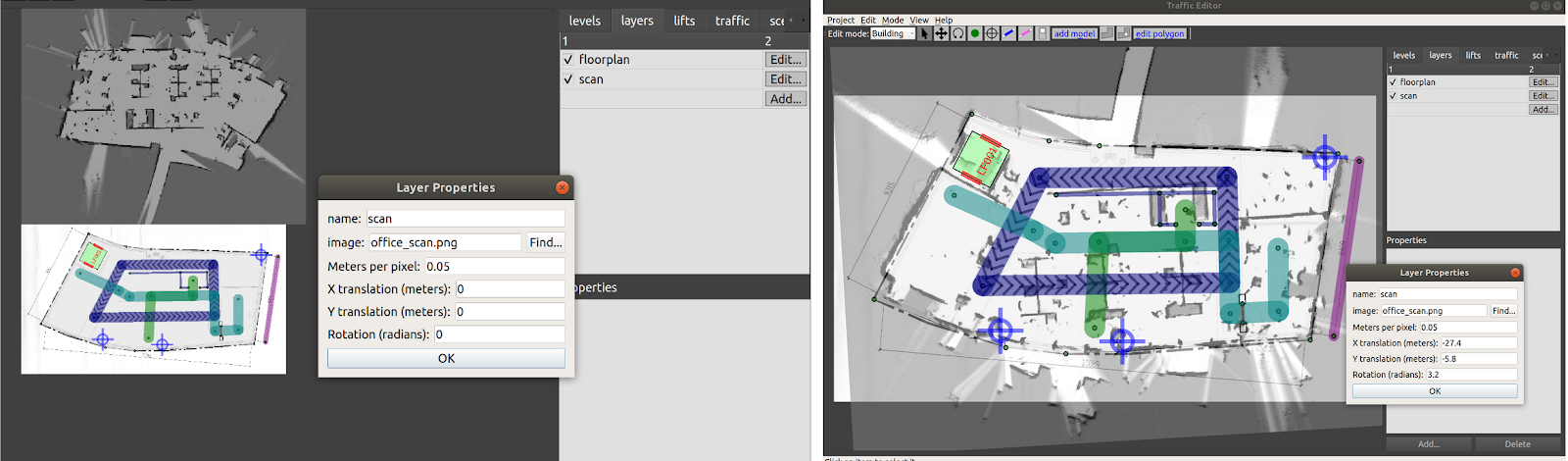
Adding fiducials
| Icon |
|---|
For maps with multiple levels, fiducials provide a means to scale and align different levels with respect to a reference level. This is crucial for ensuring dimensional accuracy of annotations across different levels and aligning the same for simulation. Fiducials are reference markers placed at locations which are expected to be vertically aligned between two or more levels. For example, structural columns may run through multiple floors and their locations are often indicated on floor plans. With two or more pairs of corresponding markers between a level and a reference level, a geometric transformation (translation, rotation and scale) may be derived between the two levels. This transformation can then be applied to all the vertices and models in the newly defined level.
To begin, add two or more non-collinear fiducials to the reference level with unique name attributes using the Add fiducial tool (left image in figure below).
In the newly created level, add the same number of fiducials at locations that are expected to be vertically aligned with matching names as the reference level (right image in figure below).
Saving and reloading the project computes the transformation between the levels which is evident from the Scale
and X-Y offsets for the new level as seen in the levels tab.
This level is now ready to be annotated.
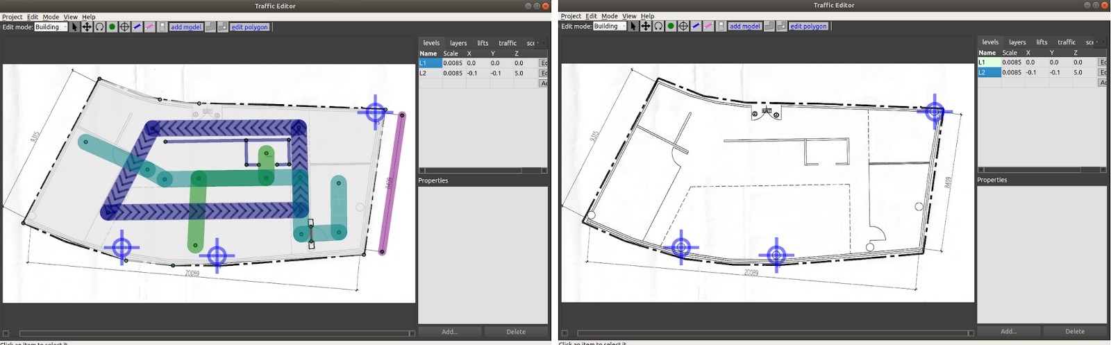
For each level, fiducials are stored in a list of their X & Y coordinates along with their name.
    fiducials:
      - [936.809, 1323.141, F1]
      - [1622.999, 1379.32, F2]
      - [2762.637, 346.69, F3]
Adding a lift
Lifts are integral resources that are shared between humans and robot fleets in multi-level facilities.
To add a lift to a building, click the Add button in the lifts tab in the Sidebar.
A dialog box with various configurable properties will load.
It is essential to specify the Name, Reference level and the X&Y coordinates (pixel units) of its cabin center.
A yaw (radians) may further be added to orient the lift as desired.
The width and depth of the cabin (meters) can also be customized.
Lifts can be designed to have multiple cabin doors which may open at more than one level.
To add a cabin door, click the Add button in the box below the cabin image.
Each cabin door requires a name along with positional and orientational information.
Here, the X&Y coordinates are relative to the cabin center.
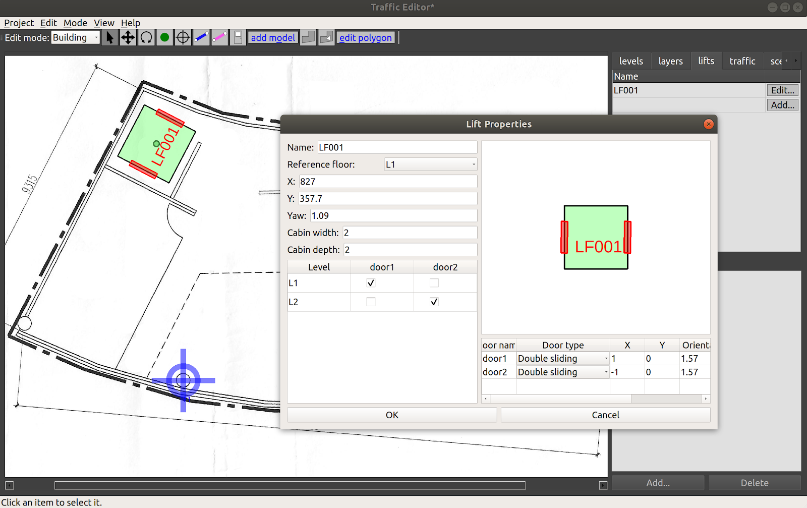
The configured lift is stored in the tutorial.building.yaml file as described below:
lifts:
  LF001:
    depth: 2
    doors:
      door1:
        door_type: 2
        motion_axis_orientation: 1.57
        width: 1
        x: 1
        y: 0
      door2:
        door_type: 2
        motion_axis_orientation: 1.57
        width: 1
        x: -1
        y: 0
    level_doors:
      L1: [door1]
      L2: [door2]
    reference_floor_name: L1
    width: 2
    x: 827
    y: 357.7
    yaw: 1.09
After adding the lift, we would also wish to let our robots to transverse through the lift. To achieve that, the user needs to create vertices/waypoints which are located within the lift cabin on each floor. Once done, connect the waypoint within the lift cabin to other vertices via add_lane.
Adding environment assets
Levels may be annotated with thumbnails of models available for simulation using the Add model tool in Building edit mode. Selecting this tool opens a dialog box with a list of model names and matching thumbnails which can be imported to the map. Once on the map, their positions and orientations can be adjusted using the Move and Rotate tools. Sample models are provided here
The thumbnail_generator documentation contains instructions on expanding the list of thumbnails for other models.
Note: If no models are shown on the add models window, Go to "Edit -> Preference", then indicate the thumbnail path. (
e.g. $HOME/rmf_ws/src/rmf/rmf_traffic_editor/rmf_traffic_editor_assets/assets/thumbnails)
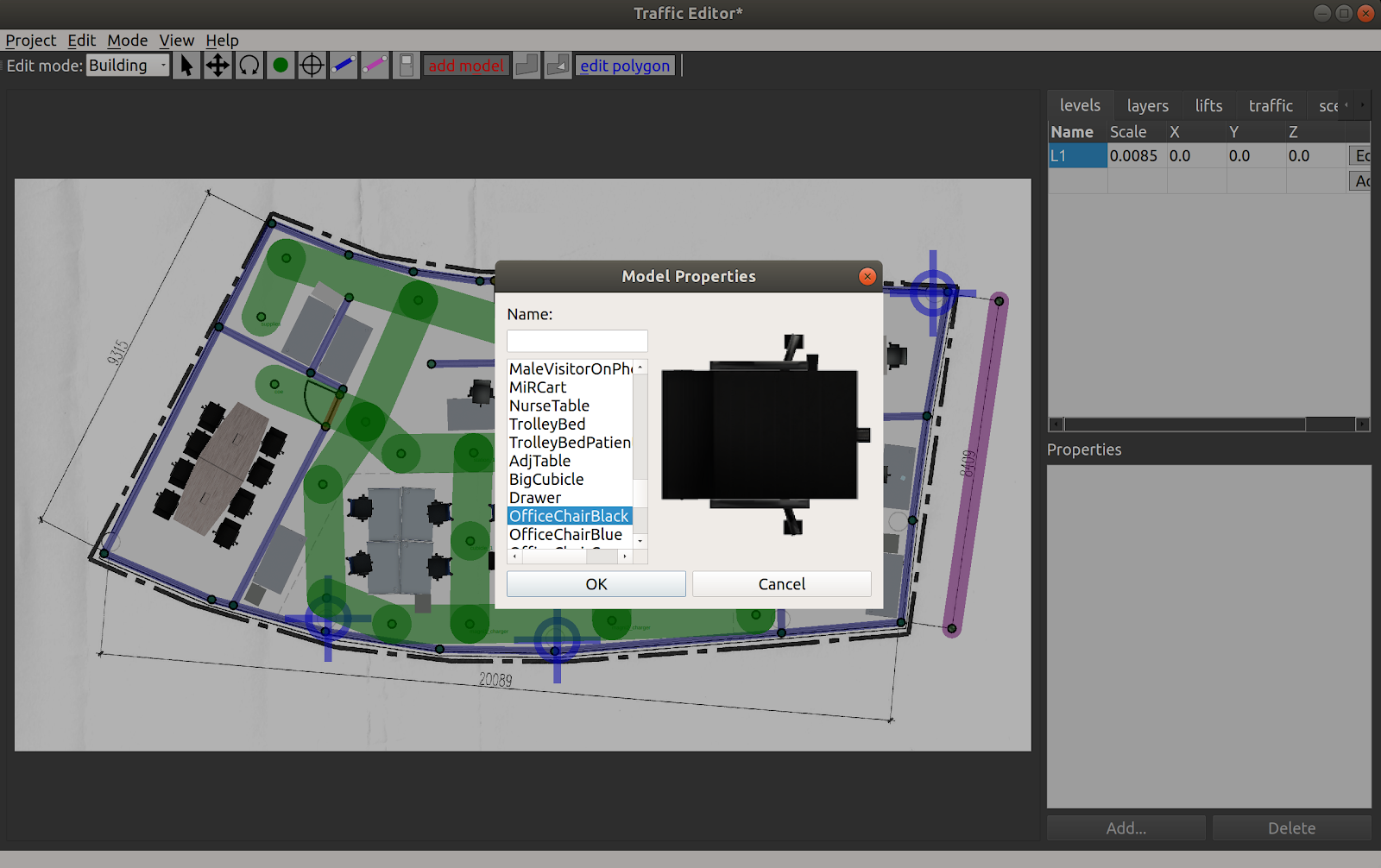
Conclusion
This chapter covered various capabilities of the traffic_editor which are useful for annotating maps of facilities while adhering to a standardized set of semantics.
Examples of other traffic editor projects can be found in the rmf_demos repository.
Running physics based simulations with RMF in the annotated sites is described in the Simulation chapter.
Simulation
This chapter describes how to generate building models from
traffic_editor files, and then simulate fleets of robots in those models.
Motivation
Simulation environments for testing robotic solutions offer immense value across various stages of R&D and deployment. More notably, simulations provide the following benefits:
-
Time and resource saving: While testing with hardware is indispensable, the process can slow development with additional setup time, robot downtime and reset periods between trials. As the number of participants scale, so do costs associated with purchasing hardware and consumables for testing. This is especially true when utilizing a solution such as RMF, which aims to integrate several mobile/stationary robots together with building systems such as doors and lifts. Simulations provide a potentially cost-effective and time-saving alternative for evaluating the behavior of robot systems at scale. More importantly, simulations can help answer questions prior to deployment such as how many participants can be supported or how the existing behavior would change with the introduction of a new fleet, both of which can inform purchasing decisions for facility owners.
-
Robust testing: Robots in simulation neither run out of battery nor incur costs when they happen to unfortunately crash into something. Scenarios can be tested for hours at a stretch, at faster speeds, to fine tune algorithms and verify their robustness. One consideration about the appropriate amount of scenario testing to run is a decision that depends on how much compute power you want to avail for the simulation. With the introduction of cloud simulation, this limit is then a trade off of cost and speed as well. As scenarios in simulation are repeatable, fixes for undesirable bugs encountered can be readily validated. Reaction of the system to edge cases which are rare but have severe consequences can also be studied through simulation. Data logged from hardware trials can be used to recreate the scenario in simulation which may be further helpful for debugging. Lastly, long running simulations can instill confidence in facility owners prior to deployment.
Physics-based simulators, such as Gazebo, carry the benefit of easily
interfacing with ROS 2 nodes through wrappers provided by gazebo_ros_pkgs.
Gazebo plugins can be developed that accurately emulate the behavior of robots,
sensors and infrastructure systems which enhance the overall fidelity of
simulations. It is worth emphasizing here that the exact same code used to run the simulations
will also be run on the physical system as well without any changes.
However, despite these compelling benefits, simulations are sparingly employed by developers and system integrators, citing complexity over generating environments and configuring them with appropriate plugins. In a recent publication "A Study on the Challenges of Using Robotics Simulators for Testing," by Afsoon Afzal, Deborah S. Katz, Claire Le Goues and Christopher S. Timperley they noted the main reasons participants gave for not using simulation for a particular project and summarized their findings as follows:
| Reason for not using simulation | # | % |
|---|---|---|
| Lack of time or resources | 15 | 53.57% |
| Not realistic/accurate enough | 15 | 53.57% |
| Lack of expertise or knowledge on how to use software-based simulation | 6 | 21.43% |
| There was no simulator for the robot | 4 | 14.29% |
| Not applicable | 4 | 14.29% |
| Too much time or compute resources | 2 | 7.14% |
| Nobody suggested it | 0 | 0.00% |
| Other | 2 | 7.14% |
The RMF project aims to address these hurdles by simplifying the process of setting up simulation environments for multi-fleet traffic control, as we will explain further throughout this section.
Building Map Generator
traffic_editor, discussed in the previous chapter, is a tool to annotate building
floor plans with fleet-specific traffic information in a vendor neutral manner.
This includes waypoints of interest, traffic lanes and shared resources such as
doorways and lifts. It can also be used to markup the walls and floors and add
thumbnails of artifacts in the environment. The ability to auto-generate a 3D
world using this annotated map is significantly valuable for simplifying the
creation and management of simulations. To this end, the building_map_tools
package in traffic_editor contains an executable building_map_generator. The
executable operates in two modes:
- Generate a Gazebo/Ignition compliant
.worldfile - Export the fleet specific traffic information in the form
of navigation graphs which are utilized by
fleet_adaptersfor planning
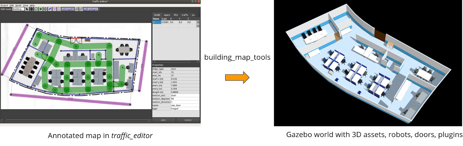
To auto-generate a Gazebo simulation world, the executable takes in the command argument gazebo along with others described below:
usage: building_map_generator gazebo [-h] [--TEMPLATE_WORLD_FILE TEMPLATE_WORLD_FILE]
                                     INPUT OUTPUT_WORLD OUTPUT_MODEL_DIR

positional arguments:
  INPUT                 Input building.yaml file to process
  OUTPUT_WORLD          Name of the .world file to output
  OUTPUT_MODEL_DIR      Path to output the map model files

options:
  -h, --help            show this help message and exit
  --TEMPLATE_WORLD_FILE TEMPLATE_WORLD_FILE
                        Specify the template for the base simulation.
The script parses the .building.yaml file and generates meshes for the
flooring and walls for each level. Those meshes are then combined into a model.sdf file in
the OUTPUT_MODEL_DIR/ directory. The model.sdf files for each level are
imported into the .world with filepath OUTPUT_WORLD. Model sub-elements for
various static objects annotated in the traffic_editor are included in the
.world as seen in the snippet below:
<include>
  <name>OfficeChairBlack_6</name>
  <uri>model://OfficeChairBlack</uri>
  <pose>4.26201267190027 -7.489812761393875 0 0 0 1.1212</pose>
  <static>True</static>
</include>
Similar blocks for annotated robots are
generated. It is the responsibility of the user to append the environment
variable $GAZEBO_MODEL_PATH with the relevant paths to the models prior to
loading the .world file in Gazebo. This process can be simplified through ROS 2
launch files and will be discussed in later sections.
The parser also includes sdf elements for other dynamic assets such as doors and lifts. Their mechanisms are discussed in the next section.
By default, the simulation world is loaded without any additional plugins. So if
you were to spawn things like cameras or lidars in your gazebo world it would not
work. This can be bypassed by using the --TEMPLATE_WORLD_FILE. This allows you
to add additional simulation assets to your world.
Reconfiguring simulation environments becomes as trivial as editing the
annotations on the 2D drawing and re-running the building_map_generator. This
is exceedingly useful to quickly evaluate traffic flow as the spatial
configuration in the facility changes.
To generate navigation graphs for fleet adapters, the building_map_generator
is executed with command argument nav. The navigation graph is generated as
a .yaml file and is parsed during launch by the corresponding fleet adapter.
usage: building_map_generator nav [-h] INPUT OUTPUT_DIR

positional arguments:
  INPUT       Input building.yaml file to process
  OUTPUT_DIR  Path to output the nav .yaml files
RMF Assets and Plugins
Assets play a pivotal role in recreating environments in simulation. Projects such as RMF, SubT and others have allowed developers to create and open source 3D models of robots, mechanical infrastructure systems and scene objects. They are available for download on the Ignition Fuel app. Beyond imparting visual accuracy, assets can be dynamic and interface with RMF core systems through the aid of plugins.
To simulate the behavior of hardware such as robot models and infrastructure systems, several Gazebo plugins have been architected. These plugins are derivatives of the ModelPlugin class and tie in standard ROS 2 and RMF core messages to provide necessary functionality. The following sections briefly describe some of these plugins.
Robots
As highlighted earlier, several robot models (SESTO, MiR100, Magni, Hospi) have been
open sourced for use in simulation. For these models to emulate the behavior of
their physical counterparts which have been integrated with RMF, they need to 1)
interface with rmf_fleet_adapters and 2) navigate to locations in the
simulated world. These functionalities, for a "full control" robot type, are
achieved through the slotcar plugin.
The plugin subscribes to /robot_path_requests and /robot_mode_requests
topics and responds to relevant PathRequest and ModeRequest messages
published by its rmf_fleet_adapter. The plugin also publishes the robot's
state to the /robot_state topic.
To navigate the robot through waypoints in a PathRequest message, a simple
"rail-like" navigation algorithm is utilized which accelerates and decelerates
the robot along a straight line from its current position to the next waypoint.
The plugin relies on these fundamental assumptions:
- The robot model is a two-wheel differential drive robot
- The left and right wheel joints are named
joint_tire_leftandjoint_tire_rightrespectively
Other parameters, the majority of which are kinematic properties of the robot, are inferred from sdf parameters:
<plugin name="slotcar" filename="libslotcar.so">
  <nominal_drive_speed>0.5</nominal_drive_speed>
  <nominal_drive_acceleration>0.25</nominal_drive_acceleration>
  <max_drive_acceleration>0.75</max_drive_acceleration>
  <nominal_turn_speed>0.6</nominal_turn_speed>
  <nominal_turn_acceleration>1.5</nominal_turn_acceleration>
  <max_turn_acceleration>2.0</max_turn_acceleration>
  <tire_radius>0.1</tire_radius>
  <base_width>0.3206</base_width>
  <stop_distance>0.75</stop_distance>
  <stop_radius>0.75</stop_radius>
</plugin>
During simulation, it is assumed that the robot's path is free of static
obstacles, but the plugin still contains logic to pause the robot's motion if an
obstacle is detected in its path. While it is possible to deploy a sensor based
navigation stack, the approach is avoided to minimize the computational load on
the system from running a navigation stack for each robot in the simulation.
Given the focus on traffic management of heterogeneous fleets and not robot
navigation, the slotcar plugin provides an efficient means to simulate the
interaction between RMF core systems and robots.
The slotcar plugin is meant to serve as a generalized solution. Vendors are
encouraged to develop and distribute plugins that represent the
capabilities of their robot and the level of integration with RMF more accurately.
Doors
Unlike robot models whose geometries are fixed and hence can be directly
included in the generated .world file, doors are custom defined in
traffic_editor and have their own generation pipeline. As seen in the figure
below, an annotated door has several properties which include the location of
its ends, the type of door (hinged, double_hinged, sliding, double_sliding) and
its range of motion (for hinged doors).
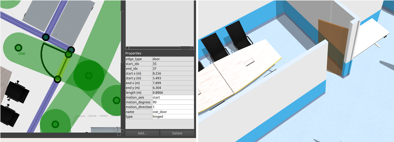
The building_map_generator gazebo script parses a .building.yaml file for
any doors and automatically generates an sdf sub-element with links and joints
required for the door along with a configured plugin. The sdf sub-element
generated for the door in the figure above is presented below.
<model name="coe_door">
  <pose>8.077686357313898 -5.898342045416362 0.0 0 0 1.1560010438234292</pose>
  <plugin filename="libdoor.so" name="door">
    <v_max_door>0.5</v_max_door>
    <a_max_door>0.3</a_max_door>
    <a_nom_door>0.15</a_nom_door>
    <dx_min_door>0.01</dx_min_door>
    <f_max_door>500.0</f_max_door>
    <door left_joint_name="left_joint" name="coe_door" right_joint_name="empty_joint" type="SwingDoor" />
  </plugin>
  <link name="left">
    <pose>0 0 1.11 0 0 0</pose>
    <visual name="left">
      <material>
        <ambient>120 60 0 0.6</ambient>
        <diffuse>120 60 0 0.6</diffuse>
      </material>
      <geometry>
        <box>
          <size>0.8766026166317483 0.03 2.2</size>
        </box>
      </geometry>
    </visual>
    <collision name="left">
      <surface>
        <contact>
          <collide_bitmask>0x02</collide_bitmask>
        </contact>
      </surface>
      <geometry>
        <box>
          <size>0.8766026166317483 0.03 2.2</size>
        </box>
      </geometry>
    </collision>
    <inertial>
      <mass>50.0</mass>
      <inertia>
        <ixx>20.17041666666667</ixx>
        <iyy>23.36846728119012</iyy>
        <izz>3.20555061452345</izz>
      </inertia>
    </inertial>
  </link>
  <joint name="left_joint" type="revolute">
    <parent>world</parent>
    <child>left</child>
    <axis>
      <xyz>0 0 1</xyz>
      <limit>
        <lower>-1.57</lower>
        <upper>0</upper>
      </limit>
    </axis>
    <pose>0.44330130831587417 0 0 0 0 0</pose>
  </joint>
</model>
The door plugin responds to DoorRequest messages with door_name matching its model name sdf tag. These messages are published over the /door_requests topic. The plugin is agnostic of the type of door defined and relies on the left_joint_name and right_joint_name parameters to determine which joints to actuate during open and close motions. During these motions, the joints are commanded to their appropriate limits which are specified in the parent element. The joint motions adhere to kinematic constraints specified by sdf parameters while following acceleration and deceleration profiles similar to the slotcar.
To avoid situations where one robot requests a door to close on another robot, a door_supervisor node is deployed in practice. The node publishes to /door_requests and subscribes to /adapter_door_requests which the fleet adapters publish to when their robot requires access through a door. The door_supervisor keeps track of requests from all the fleet adapters in the system and relays the request to the door adapters while avoiding aforementioned conflicts.
Lifts
The ability to test lift integration is crucial as these systems are often the operational bottlenecks in facilities given their shared usage by both humans and multi robot fleets. As with annotated doors, lifts can be customized in a number of ways in the traffic_editor GUI including the dimension & orientation of the cabin and mapping cabin doors to building levels.
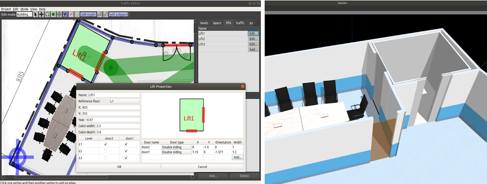
The building_map_generator gazebo script parses the .building.yaml file for lift definitions and auto-generates the sdf elements for the cabin, cabin doors and lift shaft doors.
A prismatic joint is defined at the base of the cabin which is actuated by the lift plugin to move the cabin between different levels.
While the cabin doors are part of the cabin structure, the shaft doors are fixed to the building.
Both sets of doors open and close simultaneously at a given level and are controlled by the lift plugin itself.
These doors are created using the same method as other doors in the building and include the door plugin as well.
The building_map_generator also appends a lift plugin (TODO add link element with required parameters to the lift's model sdf block.)
<plugin filename="liblift.so" name="lift">
  <lift_name>Lift1</lift_name>
  <floor elevation="0.0" name="L1">
    <door_pair cabin_door="CabinDoor_Lift1_door1" shaft_door="ShaftDoor_Lift1_L1_door1" />
  </floor>
  <floor elevation="10.0" name="L2">
    <door_pair cabin_door="CabinDoor_Lift1_door1" shaft_door="ShaftDoor_Lift1_L2_door1" />
    <door_pair cabin_door="CabinDoor_Lift1_door2" shaft_door="ShaftDoor_Lift1_L2_door2" />
  </floor>
  <floor elevation="20.0" name="L3">
    <door_pair cabin_door="CabinDoor_Lift1_door1" shaft_door="ShaftDoor_Lift1_L3_door1" />
  </floor>
  <reference_floor>L1</reference_floor>
  <v_max_cabin>2.0</v_max_cabin>
  <a_max_cabin>1.2</a_max_cabin>
  <a_nom_cabin>1.0</a_nom_cabin>
  <dx_min_cabin>0.001</dx_min_cabin>
  <f_max_cabin>25323.0</f_max_cabin>
  <cabin_joint_name>cabin_joint</cabin_joint_name>
</plugin>
The plugin subscribes to /lift_requests topic and responds to LiftRequest messages with lift_name matching its model name sdf tag.
The displacement between the cabin's current elevation and that of the destination_floor is computed and a suitable velocity is applied to the cabin joint.
Prior to any motion, the cabin doors are closed and only opened at the destination_floor if specified in the LiftRequest message.
As the cabin and shaft doors are configured with the door plugin, they are commanded through DoorRequest messages published by the lift plugin.
Analogous to the door_supervisor, a lift_supervisor node is started in practice to manage requests from different robot fleets.
Workcells
A common use case is robots performing deliveries within facilities, so a Delivery task is configured into the rmf_fleet_adapters.
In a delivery task, a payload is loaded onto the robot at one location (pickup waypoint) and unloaded at another (dropoff waypoint).
The loading and unloading of the payload onto and from a robot may be automated by robots/workcells in the facility. These devices are henceforth referred to as dispensers and ingestors respectively.
To replicate the loading and unloading processes in simulation, the TeleportDispenser and TeleportIngestor plugins have been designed.
These plugins are attached to the TeleportDispenser and TeleportIngestor 3D models, respectively.
To setup a payload loading station in simulation:
- Add a
TeleportDispensermodel beside the pickup waypoint and assign it a uniquename - Add the payload model beside the
TeleportDispensermodel (Coke can in image below)
To setup a payload unloading station in simulation:
- Add a
TeleportIngestormodel beside the dropoff waypoint and assign it a uniquename
When a DispenserRequest message is published with target_guid matching the
name of the TeleportDispenser model, the plugin will teleport the payload onto
the nearest robot model. Conversely, when an IngestorRequest message is published
with the target_guid matching the name of the TeleportIngestor model, the
TeleportIngestor plugin will teleport the payload from the robot to its location in
the world. The combinations of these plugins allow delivery requests to be simulated.
In the future, these mechanisms will be replaced by actual workcells or robot arms
but the underlying message exchanges will remain the same.
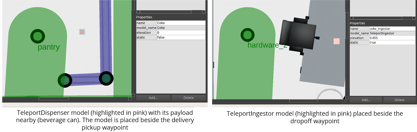
Crowdsim
Crowd Simulation, aka CrowdSim is an optional feature in RMF simulation. User can
choose to enable crowdsim on rmf_traffic_editor. In RMF, the crowdsim plugin uses
menge as the core to control each of
simulated agent in the world.
An example of crowdsim is demonstrated on rmf_demos's airport_world:
ros2 launch rmf_demos_gz airport_terminal.launch.xml use_crowdsim:=1
For more details on how crowdsim works and how to configure it,
please dive in to the detailed guide for using Crowdsim.
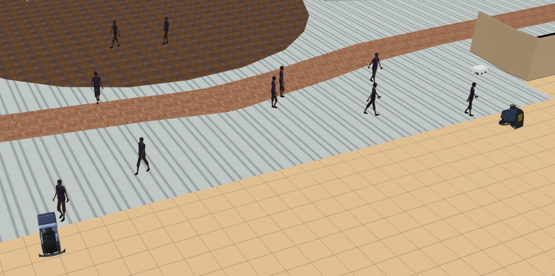
Creating Simulations and Running Scenarios
The section aims to provide an overview of the various components in the rmf_demos repository which may serve as a reference for setting up other simulations and assigning tasks to robots. Here, we will focus on the office world.
Map package
The rmf_demos_maps package houses annotated traffic_editor files which will be used for the 3D world generation. Opening the office.project.yaml file in traffic_editor reveals a single level floorplan that has walls, floors, scale measurements, doors, lanes and models annotated. All the robot lanes are set to bidirectional with graph_idx equal to "0". The latter signifies that all the lanes belong to the same fleet. In the airport world, we have two sets of graphs with indices "0" and "1" which reflect laneways occupiable by two fleets respectively. The figure below highlights properties assigned to a lane and a waypoint that serves as a robot spawn location.

To export a 3D world file along with the navigation graphs, the building_map_generator script is used. The CMakeLists.txt file of this package is configured to automatically run the generator scripts when the package is built. The outputs are installed to the share/ directory for the package. This allows for the generated files to be easily located and used by other packages in the demo.
foreach(path ${traffic_editor_paths})

  # Get the output world name
  string(REPLACE "." ";" list1 ${path})
  list(GET list1 0 name)
  string(REPLACE "/" ";" list2 ${name})
  list(GET list2 -1 world_name)

  set(map_path ${path})
  set(output_world_name ${world_name})
  set(output_dir ${CMAKE_CURRENT_BINARY_DIR}/maps/${output_world_name})
  set(output_world_path ${output_dir}/${output_world_name}.world)
  set(output_model_dir ${output_dir}/models)

  # first, generate the world
  add_custom_command(
    OUTPUT ${output_world_path}
    COMMAND ros2 run rmf_building_map_tools building_map_generator gazebo ${map_path} ${output_world_path} ${output_model_dir}
    DEPENDS ${map_path}
  )

  add_custom_target(generate_${output_world_name} ALL
    DEPENDS ${output_world_path}
  )

  # now, generate the nav graphs
  set(output_nav_graphs_dir ${output_dir}/nav_graphs/)
  set(output_nav_graphs_phony ${output_nav_graphs_dir}/phony)
  add_custom_command(
    OUTPUT ${output_nav_graphs_phony}
    COMMAND ros2 run rmf_building_map_tools building_map_generator nav ${map_path} ${output_nav_graphs_dir}
    DEPENDS ${map_path}
  )

  add_custom_target(generate_${output_world_name}_nav_graphs ALL
    DEPENDS ${output_nav_graphs_phony}
  )

  install(
    DIRECTORY ${output_dir}
    DESTINATION share/${PROJECT_NAME}/maps
  )

endforeach()
Launch Files
The rmf_demos package includes all the essential launch files required to bring up the simulation world and start various RMF services. The office simulation is launched using the office.launch.xml file. First, a common.launch.xml file is loaded and starts:
- The
rmf_traffic_schedulenode responsible for maintaining the database of robot trajectories and monitoring traffic for conflicts. If a conflict is detected, notifications are sent to relevant fleet adapters which begin the negotiation process to find an optimal resolution. - The
building_map_serverwhich publishes aBuildingMapmessage used by UIs for visualization. The executable takes in the path to the relevant.building.yamlfile as an argument. Theoffice.building.yamlfile installed by thermf_demos_mapspackage is located using thefind-pkg-sharesubstitution command and is stored in theconfig_fileargument. - The
rmf_schedule_visualizerwhich is an RViz based UI to visualize the traffic lanes, actual positions of the robots, expected trajectory of robots as reflected in thermf_traffic_scheduleand states of building systems such as door and lifts. - The
door_supervisorandlift_supervisornodes to manage requests submitted by fleet adapter and UIs.
<!-- Common launch -->
<include file="$(find-pkg-share demos)/common.launch.xml">
  <arg name="use_sim_time" value="true"/>
  <arg name="viz_config_file" value ="$(find-pkg-share demos)/include/office/office.rviz"/>
  <arg name="config_file" value="$(find-pkg-share rmf_demos_maps)/office/office.building.yaml"/>
</include>
To launch a simulated world in gazebo, a snippet from rmf_demos_gz is shown below. Similarly, user can also choose to run with ignition simulator, rmf_demos_ign
  <group>
    <let name="world_path" value="$(find-pkg-share rmf_demos_maps)/maps/office/office.world" />
    <let name="model_path" value="$(find-pkg-share rmf_demos_maps)/maps/office/models:$(find-pkg-share rmf_demos_assets)/models:/usr/share/gazebo-9/models" />
    <let name="resource_path" value="$(find-pkg-share rmf_demos_assets):/usr/share/gazebo-9" />
    <let name="plugin_path" value="$(find-pkg-prefix rmf_gazebo_plugins)/lib:$(find-pkg-prefix building_gazebo_plugins)/lib" />

    <executable cmd="gzserver --verbose -s libgazebo_ros_factory.so -s libgazebo_ros_init.so $(var world_path)" output="both">
      <env name="GAZEBO_MODEL_PATH" value="$(var model_path)" />
      <env name="GAZEBO_RESOURCE_PATH" value="$(var resource_path)" />
      <env name="GAZEBO_PLUGIN_PATH" value="$(var plugin_path)" />
      <env name="GAZEBO_MODEL_DATABASE_URI" value="" />
    </executable>
    <executable cmd="gzclient --verbose $(var world_path)" output="both">
      <env name="GAZEBO_MODEL_PATH" value="$(var model_path)" />
      <env name="GAZEBO_RESOURCE_PATH" value="$(var resource_path)" />
      <env name="GAZEBO_PLUGIN_PATH" value="$(var plugin_path)" />
    </executable>
  </group>
Lastly, instances of the "full control" rmf_fleet_adapter are launched for each robot type annotated in the map. The navigation graphs for each fleet as generated by the building_map_generator script is passed via the nav_graph_file argument. For the office map, a single fleet of Magni robots is defined. Hence, a single magni_adapter.launch.xml file configured with the kinematic properties of this robot type along with spatial thresholds used for planning, is launched. Along with the fleet adapter, a robot_state_aggregator node is started. This node aggregates RobotState messages with RobotState.name containing the robot_prefix argument and publishes the aggregate to /fleet_states with FleetState.name specified by the fleet_name argument.
<group>
  <let name="fleet_name" value="magni"/>
  <include file="$(find-pkg-share rmf_demos)/include/adapters/magni_adapter.launch.xml">
    <arg name="fleet_name" value="$(var fleet_name)"/>
    <arg name="use_sim_time" value="$(var use_sim_time)"/>
    <arg name="nav_graph_file" value="$(find-pkg-share rmf_demos_maps)/maps/office/nav_graphs/0.yaml" />
  </include>
  <include file="$(find-pkg-share rmf_fleet_adapter)/robot_state_aggregator.launch.xml">
    <arg name="robot_prefix" value="magni"/>
    <arg name="fleet_name" value="$(var fleet_name)"/>
    <arg name="use_sim_time" value="true"/>
  </include>
</group>
When testing RMF with hardware, the same launch files can be used, with the exception of starting Gazebo.
More information on running demos with hardware can be found the chapter on Integration.
Task Requests
RMF supports various tasks out of the box. For more information see Tasks in RMF A web-based dashboard is provided to allow users to send commands to RMF. Once the dashboard server is launched, it can be accessed at https://open-rmf.github.io/rmf-panel-js/.

Alternatively several scripts exist in rmf_demos_tasks to assist users with submitting requests from the terminal. Presently the dispatch_loop.py, dispatch_delivery.py and dispatch_clean.py scripts can be used to submit Loop, Delivery and Clean requests.
Conclusion
This chapter covered the utilization of the traffic_editor tool to create annotated maps that allow the auto-generation of 3D worlds for simulations.
It also covered the assets used within simulations and the corresponding plugins necessary for ROS 2 and RMF to interface with them.
A working example of these components running together, in the form of the rmf_demos_maps package, was provided as a reference for how to actualize a custom system.
The next chapter will introduces the basic concept behind RMF.
RMF Core Overview
This chapter describes RMF, an umbrella term for a wide range of open specifications and software
tools that aim to ease the integration and interoperability of robotic systems,
building infrastructure, and user interfaces. rmf_core consists of:
- rmf_traffic: Core scheduling and traffic management systems
- rmf_traffic_ros2: rmf_traffic for ros2
- rmf_task: Task planner for rmf
- rmf_battery: rmf battery estimation
- rmf_ros2: ros2 adapters and nodes and python bindings for rmf_core
- rmf_utils: utility for rmf
Traffic deconfliction
Avoiding mobile robot traffic conflicts is a key functionality of rmf_core.
There are two levels to traffic deconfliction: (1) prevention, and (2)
resolution.
Prevention
Preventing traffic conflicts whenever possible is the best-case scenario.
To facilitate traffic conflict prevention, we have implemented a
platform-agnostic Traffic Schedule Database. The traffic schedule is a living
database whose contents will change over time to reflect delays, cancellations,
or route changes. All fleet managers that are integrated into an RMF deployment must
report the expected itineraries of their vehicles to the traffic schedule. With
the information available on the schedule, compliant fleet managers can plan
routes for their vehicles that avoid conflicts with any other vehicles, no
matter which fleet they belong to. rmf_traffic provides a
Planner
class to help facilitate this for vehicles that behave like standard AGVs (Automated Guided Vehicles),
rigidly following routes along a pre-determined grid. In the future
we intend to provide a similar utility for AMRs (Autonomous Mobile Robots) that can perform ad hoc motion
planning around unanticipated obstacles.
Negotiation
It is not always possible to perfectly prevent traffic conflicts.
Mobile robots may experience delays because of unanticipated obstacles in their
environment, or the predicted schedule may be flawed for any number of reasons.
In cases where a conflict does arise, rmf_traffic has a Negotiation scheme.
When the Traffic Schedule Database detects an upcoming conflict between two or
more schedule participants, it will send a conflict notice out to the relevant
fleet managers, and a negotiation between the fleet managers will begin. Each
fleet manager will submit its preferred itineraries, and each will respond with
itineraries that can accommodate the others. A third-party judge (deployed by
the system integrator) will choose the set of proposals that is considered
preferable and notify the fleet managers about which itineraries they should
follow.
There may be situations where a sudden, urgent task needs to take place (for example, a response to an emergency), and the current traffic schedule does not accommodate it in a timely manner. In such a situation, a traffic participant may intentionally post a traffic conflict onto the schedule and force a negotiation to take place. The negotiation can be forced to choose an itinerary arrangement that favors the emergency task by implementing the third-party judge to always favor the high-priority participant.
Traffic Schedule
The traffic schedule is a centralized database of all the intended robot traffic trajectories in a facility. Note that it contains the intended trajectories; it is looking into the future. The job of the schedule is to identify conflicts in the intentions of the different robot fleets and notify the fleets when a conflict is identified. Upon receiving the notification, the fleets will begin a traffic negotiation, as described above.
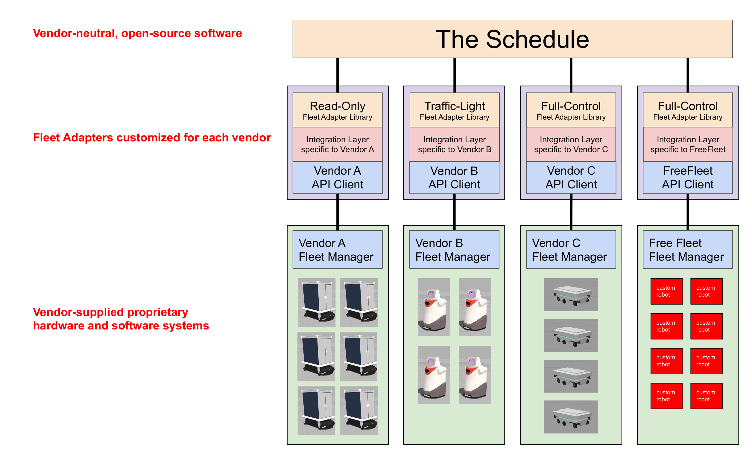
Fleet Adapters
Each robot fleet that participates in an RMF deployment is expected to have a fleet adapter that connects its fleet-specific API to the interfaces of the core RMF traffic scheduling and negotiation system. The fleet adapter is also responsible for handling communication between the fleet and the various standardized smart infrastructure interfaces, e.g. to open doors, summon lifts, and wake up dispensers.
Different robot fleets have different features and capabilities, dependent on how they were designed and developed. The traffic scheduling and negotiation system does not postulate assumptions about what the capabilities of the fleets will be. However, to minimize the duplication of integration effort, we have identified 4 different broad categories of control that we expect to encounter among various real-world fleet managers.
| Fleet adapter type | Robot/Fleetmanager API feature set | Remarks |
|---|---|---|
Full Control |
| RMF is provided with live status updates and full control over the paths that each individual mobile robot uses when navigating through the environment. This control level provides the highest overall efficiency and compliance with RMF, which allows RMF to minimize stoppages and deal with unexpected scenarios gracefully. (API available) |
Traffic Light |
| RMF is given the status as well as pause/resume control over each mobile robot, which is useful for deconflicting traffic schedules especially when sharing resources like corridors, lifts and doors. *(API available) |
Read Only |
| RMF is not given any control over the mobile robots but is provided with regular status updates. This will allow other mobile robot fleets with higher control levels to avoid conflicts with this fleet. Note that any shared space is allowed to have a maximum of just one "Read Only" fleet in operation. Having none is ideal. (Preliminary API available) |
No Interface | Without any interface to the fleet, other fleets cannot coordinate with it through RMF, and will likely result in deadlocks when sharing the same navigable environment or resource. This level will not function with an RMF-enabled environment. (Not compatible) |
In short, the more collaborative a fleet is with RMF, the more harmoniously all of the fleets and systems are able to operate together. Note again that there can only ever be one "Read Only" fleet in a shared space, as any two or more of such fleets will make avoiding deadlock or resource conflict nearly impossible.
Currently we provide a reusable C++ API (as well as Python bindings) for integrating the Full Control category of fleet management. A preliminary ROS 2 message API is available for the Read Only category, but that API will be deprecated in favor of a C++ API (with Python bindings available) in a future release. The Traffic Light control category is compatible with the core RMF scheduling system, but we have not yet implemented a reusable API for it. To implement a Traffic Light fleet adapter, a system integrator would have to use the core traffic schedule and negotiation APIs directly, as well as implement the integration with the various infrastructure APIs (e.g. doors, lifts, and dispensers).
The API for the Full Control category is described in the Mobile Robot Fleets section of the Integration chapter, and the Read Only category is described in the Read Only Fleets section of the Integration chapter.
Frequently Asked Questions
Why is this traffic management system so complicated?
RMF has a number of system design constraints that create unique challenges for traffic management. The core goal of RMF is to facilitate system integration for heterogeneous mobile robot fleets that may be provided by different vendors and may have different technical capabilities.
Vendors tend to want to keep their computing systems independent from other vendors. Since vendors are often responsible for ensuring uptime and reliability on their computing infrastructure, they may view it as an unacceptable liability to share computing resources with another vendor. This means that the traffic management system must be able to function while being distributed across different machines on a network.
Different robot platforms may have different capabilities. Many valuable AGV platforms that are currently deployed are not able to change their itineraries dynamically. Some AGV platforms can change course when instructed to, as long as they stick to a predefined navigation graph. Some AMR platforms can dynamically navigate themselves around unanticipated obstacles in their environment. Since RMF is meant to be an enabling technology, it is important that we design a system that can maximize the utility of all these different types of systems without placing detrimental constraints on any of them.
These considerations led to the current design of distributed conflict prevention and distributed schedule negotiation. There is plenty of space within the design to create simpler and more efficient subsets for categories of mobile robots that fit certain sets of requirements, but these optimizations can be added later, building on top of the existing completely generalized framework.
Who opens and closes doors and operates the lifts? The robot or RMF? Or both?
The responsibility of knowing when a door needs to be opened and then sending the command to open it belongs to the "fleet adapter". The basic design is:
- The fleet adapter keeps track of the robot's progress
- When the robot needs to go through a door, the fleet adapter will recognize this
- The fleet adapter will send a signal to the door to open
- Once the door is open, the fleet adapter will command the robot to proceed
- Once the robot is through the door, the fleet adapter will command the robot wait until the door is closed
- The fleet adapter will command the door to close
- Once the door is closed, the fleet adapter will command the robot to proceed
The way a fleet adapter knows about the doors is by parsing the navigation
graph that is provided to it. The navigation graph is a required parameter for
the full_control type of fleet adapter. rmf_demos shows an example of
providing a navigation graph to the fleet adapter.
The recommended way to construct a navigation graph is to use the
traffic-editor tool. The rmf_demos repos shows some examples of
traffic-editor project files.
However, it's entirely possible to construct your own navigation graphs. They use YAML format.
Are lifts supported?
Proper lift support (meaning, specifying an actual lift that can move between floors, and exporting that information into the navigation graph) is not something that has been developed yet.
However, for testing and demonstration purposes, there are two special navigation graph edge properties that can allow a RMF fleet adapter to emulate lift usage. This is meant for demo scenarios where a "mock lift" has been created that receives lift commands and transmits lift states but does not actually move between any different floors in a building. For example, tape on the floor of a lab to indicate the "lift cabin" box, to allow development and testing without occupying the actual building lift.
These properties were initially included for demonstration purposes, but they are proving useful enough that we might make them officially supported properties. Due to the cost and scarcity of "real" lifts, there seems to be broad interest in having single-floor hardware test setups that emulate multi-floor scenarios.
The edge properties are:
demo_mock_floor_name: The name of the floor that the robot is on while traversing the edgedemo_mock_lift_name: The name of the lift that is being entered or exited while the robot traverses the edge
The idea is that if you have a single floor demonstration environment but want to demonstrate interaction with a lift, then you can set up a mock "lift" and imagine that each side of the "lift" opens to a different floor, and the robot is only allowed to enter/exit that side of the "lift" when the "lift" believes it is on that floor. This emulates lift cabins with two sets of doors.
To make this idea more concrete, imagine you have a single-floor hardware testing area, and a box is drawn on the ground with an LED display next to it that reads off pretend floor names. The mock lift will transmit lift state messages that match up with whatever floor the LED is displaying. There is also some indication of whether the lift doors are open or closed. You can further imagine that entering or exiting from west side of the "lift" is only allowed when the lift believes it is on floor L1 whereas entering or exiting the "lift" from the east side is only allowed when it believes it is on floor L3.
In that setup, for a robot to "correctly" navigate from a waypoint on L1 to a waypoint on L3, the robot needs to:
- Approach the "lift" from the west side
- Call the "lift" down to L1
- Wait until the lift state has it on floor L1 with the doors open
- Move into the "lift" (i.e. the box drawn on the ground) and request that it "moves" to L3
- Wait until the "lift" indicates that it has reached L3 and that its doors are open
- Exit the "lift" on the east side
A rough ASCII diagram would look like this (numbers are waypoints and letters are edges):
1 <---a---> 2 <---b---> 3
- Waypoint 1 is on floor L1
- Waypoint 2 is inside the "lift" named LIFT001
- Waypoint 3 is on floor L3
- The properties of edge
aare:- bidirectional: true
- demo_mock_floor_name: L1
- demo_mock_lift_name: LIFT001
- The properties of edge
bare:- bidirectional: true
- demo_mock_floor_name: L3
- demo_mock_lift_name: LIFT001
If multiple fleets can do the same task, which one is one chosen?
Though not implemented yet, there is a design worked out for a bidding system where a task request will be converted to a bid request. The bid request will be sent to each fleet adapter, and each fleet adapter that can perform the task will report its best estimate for how soon it would be able to have the task finished. The fleet adapter that offers the lowest bid will be assigned the task.
The API and implementation are awaiting finalization of some critical components.
Can some robots have priority over other robots?
The negotiation system concept does support prioritization for which robot will accommodate the other robot(s). Any arbitrary metric or weighting system can be used when resolving a negotiation. But in the current implementation that we are using, we treat all vehicles as equal and choose the resolution that minimizes the net delay across all the robots, without any prioritization or weighting.
Since this codebase is open source, you can easily fork the code and modify it
to use any prioritization system that you'd like. Specifically, replace
rmf_traffic::schedule::QuickestFinishEvaluator() with your own
Negotiation::Evaluator class that behaves in whatever way you would like.
What distance is maintained between two robots?
This is configurable. There are two relevant parameters: footprint_radius and
vicinity_radius. The footprint_radius represents an estimate of the
vehicle's physical footprint. The vicinity_radius represents an estimate of
the region which the robot needs other vehicles to stay clear of. A "schedule
conflict" is defined as an instance where one vehicle's "footprint" is
scheduled to enter another vehicle's "vicinity". The job of the negotiation
system is to come up with a fix to the schedule that keeps all vehicles'
"footprints" out of all other vehicles' "vicinities".
How is job dispatching accomplished?
The Dispatch Planner module is currently a work-in-progress. So far, the demo platforms that have been developed for RMF did not require a planner to dispatch tasks to different fleets, because in all demo platforms done thus far (late 2020), each task type could only be performed by one (and only one) robot fleet. So the task dispatching has been trivial: the task gets assigned to whatever fleet is capable of performing the task, while the rest of the fleets just ignore the task request. We are currently working on a true dispatch planner and formal task bidding system which we're aiming to include in release 1.2.0, slated for end of December 2020. The idea is that every fleet that can perform a task request will offer a bid for how much it would "cost" them to perform a task, and the bid with the lowest "cost" will be the winner. The "cost" will be determined by two factors:
- How quickly the task is finished
- How much other tasks get delayed if the new task needs to preempt them
What is rmf_traffic ?
rmf_traffic provides a middleware-neutral implementation of the core traffic scheduling algorithms and utilities. It does not use or depend on ROS 2.
What is rmf_traffic_ros2 ?
rmf_traffic_ros2 provides convenient wrappers for using the rmf_traffic as part of a distributed ROS 2 system.
Where is the costmap?
There is no costmap representation in rmf_core.
Costmaps are one method that is typically used for representing volume occupancy for autonomous navigation planning.
While it's true that the traffic utilities deal with navigation planning, they are principally concerned about identifying conflicts between the intended routes of autonomous vehicles.
The traffic utilities are not responsible for the "local" navigation of vehicles around static obstacles in their environment.
Different robot platforms often have different representations of costmaps or other navigation algorithms, many of which may be proprietary.
On top of that, different robot platforms with the same costmap representations may still require different costmap values because of differences in robot footprints.
Because of these factors, we leave it to the robot platforms themselves to determine how they represent their costmaps. If it's important for a system integrator to take a robot's costmap into account when performing traffic planning, they can implement a custom rmf_traffic::agv::RouteValidator that uses the robot's custom costmap when determining whether a candidate route is valid.
What is the core algorithm behind rmf_traffic ?
Conflict avoidance for AGV's in rmf_traffic is implemented with time-dependent extension to A* search
This search takes time into account so that it can find paths through space and time that account for the motions of other agents that are in the traffic schedule.
During negotiation, how do fleets compute their proposals?
Because the system is designed to be extensible and adaptable to a wide variety of scenarios and robot vendor combinations, including many that do not currently exist, it has many pieces and hooks for expansion. The sequence of computing a traffic proposal is as follows:
- First, the fleet adapter node will receive a conflict notification which tells it that it needs to participate in a negotiation to resolve a space-time conflict. This notification is received by the
rmf_traffic_ros2::schedule::Negotiationclass. - For this to happen, the fleet adapter creates a negotiation-notification subscription, so that it will be told whenever a particular robot under its control needs to respond to a negotiation notification.
- When a robot needs to repond to a negotiation, its implementation gets triggered.
- This implementation will launch a multi-threaded
Negotiateservice, whose main implementation can be found here
Every step in the multi-party negotiation is using the Negotiate service the exact same way.
The only difference between the various steps is what constraints they need to deal with.
Those constraints are described by the rmf_traffic::schedule::Negotiation::Table::Viewer object that gets passed to the respond(~) function.
Because the same object can be used to describe the constraints of all the different blocks in the diagram, we can use the same code to solve every block.
There are also reject and forfeit code paths that may be invoked as necessary:
- The "rejection" mechanism is used when it's impossible for one of the fleets to accommodate a proposal that came from another. When a rejection is performed, the rejecting fleet will provide a set of feasible trajectories (usually anywhere from 10-200 trajectories) and the fleet that receives the rejection should try once again to find an ideal proposal for itself, but that ideal proposal must accommodate at least one of the trajectory alternatives that were provided with the rejection.
- The "forfeit" mechanism is used when the planner is having an inordinately difficult time finding any kind of solution. This can happen when the negotiation has numerous participants that are all actively on the move, which can lead to situations that are seemingly impossible to resolve due to inconsistencies across time. Typically, when a forfeit is used, there will be another feasible combination of accommodations that gets found by the negotiation. In the worst case scenario, if negotiations keep failing, the robots may experience a real-life deadlock. When a deadlock happens, the participants will be sitting still so the negotiation will reach a steady state and will not be negatively affected by async inconsistencies. When that happens, a successful resolution is practically assured.
The preceeding explanation describes the "Full Control" style of fleet adapter. The implementation for the "Read Only" and "Traffic Light" APIs are a bit different.
Tasks in RMF
RMF simplifies task allocation and management across multi-fleet systems. When a user submits a new task request, RMF will intelligently assign it to the robot in the fleet that can best perform the task. When
RMF supports three types of task requests out of the box:
- Clean: For robots capable of cleaning floor spaces in facilities
- Delivery: For robots capable of delivering items between locations in facilities
- Loop: For robots capable to navigating back and forth between locations in facilities
Note: A single robot may be capable of performing one of more of the above tasks and fleet adapters can be configured to reflect the capability of its robots. For more information on the supported task types, click here
In RMF version 21.04 and above, tasks are awarded to robot fleets based on the outcome of a bidding process that is orchestrated by a Dispatcher node, rmf_dispatcher_node.
When the Dispatcher receives a new task request from a dashboard or terminal, it sends out a rmf_task_msgs/BidNotice message to all the fleet adapters. If a fleet adapter is able to process that request, it submits a rmf_task_msgs/BidProposal message back to the Dispatcher with a cost to accommodate the task. An instance of rmf_task::agv::TaskPlanner is used by the fleet adapters to determine how best to accommodate the new request. For more information on the task planner, click here
The Dispatcher then compares all the BidProposals received and submits a rmf_task_msgs/DispatchRequest message with the fleet name of the robot that the bid is awarded to. There are a couple different ways the Dispatcher evaluates the proposals such as fastest to finish, lowest cost, etc which can be configured.
Battery recharging is tightly integrated with the new task planner. ChargeBattery tasks are optimally injected into a robot's schedule when the robot has insufficient charge to fulfill a series of tasks. Currently we assume each robot in the map has a dedicated charging location as annotated with the is_charger option in the traffic editor map.
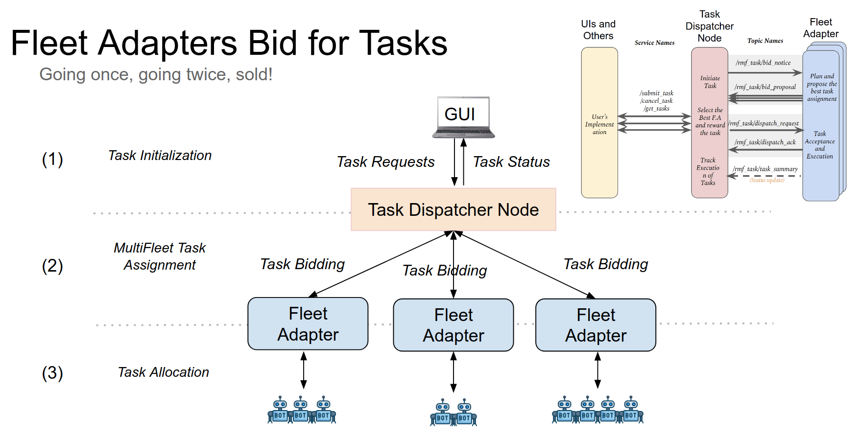
RMF Task Allocation Planner
Coming soon...
Supported Tasks in RMF
Clean Task:
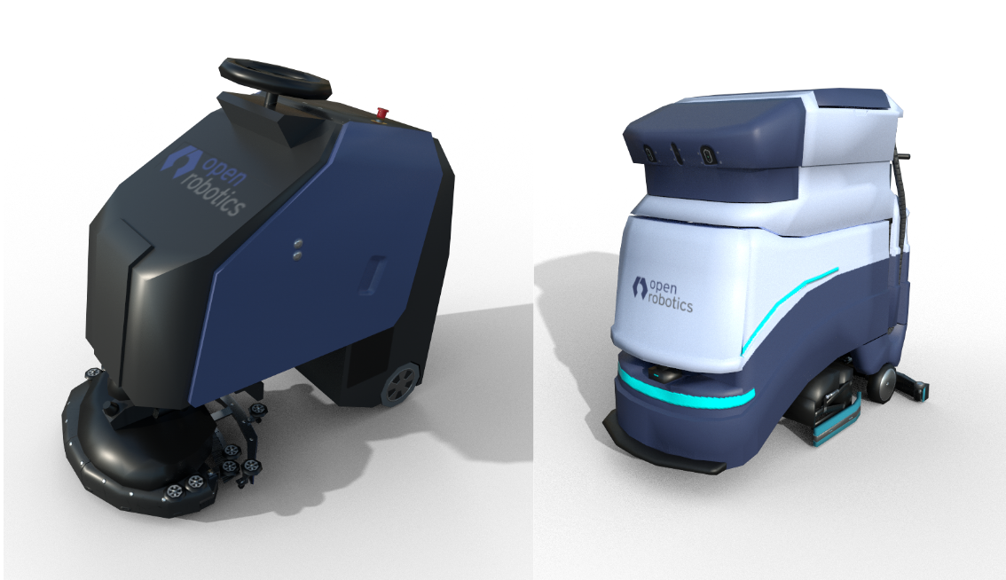
Cleaning robots are becoming increasingly popular in various facilities. While there are many ways of cleaning (vacuuming, mopping, disinfecting, etc) and hence many varieties of cleaning robots, the workflow remains identical across them all. Floor space in facilities is divided into a number of “zones” or sub-regions for cleaning. Each zone has a start and finish location for the robot. In-between these locations, the robot traverses along a special path while performing the cleaning operation.
RMF fully supports the integration of various cleaning robots. Further, RMF can intelligently assign cleaning jobs to available cleaning robots based on capability and available resources, while optimizing overall productivity. Most cleaning robots have a pre-configured cleaning routine for each zone that can be run from a given starting point. RMF’s goal is to guide the robot to this starting point, trigger the execution of the cleaning routine and then guide the robot to a holding waypoint once the cleaning is complete. A Clean Task has been designed in RMF to orchestrate this behavior.
The rest of this section provides an overview of the steps necessary to integrate cleaning robots with RMF. The airport_terminal example in rmf_demos is a useful reference. It showcases the integration of two brands of cleaning robots: CleanerBotA and CleanerBotE which operate on navigation graphs Graph 0 and Graph 4 respectively.
Step 1: Defining waypoints for cleaning in Traffic Editor
Two waypoints need to be added to the navigation graph of the robot. The first is the waypoint where the robot should initiate its cleaning routine. In the image below, this point is labelled as zone_1_start. Once the robot finishes its cleaning routine, RMF will guide the robot back to this waypoint. Connected to this waypoint, is waypoint zone_1 that has the dock_name property set to its name. This is the waypoint where the robot ends up after its cleaning routine is completed. In the current implementation, it is important to have the names of these waypoints as <zone_name>_start and <zone_name> respectively. When a robot enters the lane from zone_1_start to zone_1, the fleet adapter will request the robot to initiate its docking (in this case cleaning) routine. Setting the dock_name parameter to zone_1 will result in the fleet adapter triggering the RobotCommandHandle::dock() function. Thus, the user’s implementation of this function should in-turn make an API call to the robot to begin cleaning the specified zone. Once the cleaning process is completed, the RobotCommandHandle should trigger the docking_finished_callback().
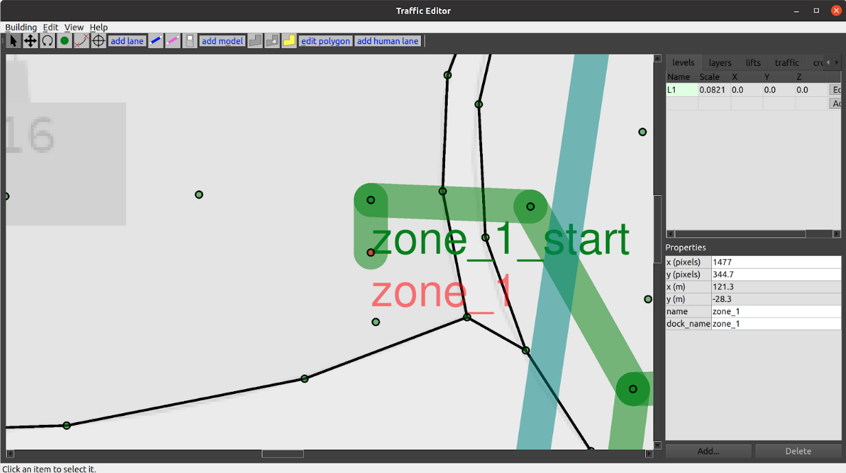
Note: In order to trigger the
DockPhase, the direction of the lane is required to be from<zone_name>_startto<zone_name>.
Step 2: Publish DockSummary message
To estimate the resource drain from the cleaning process which is essential for optimal task allocation planning, the fleet adapters require the list of waypoints that the robot will traverse while cleaning.
This information can be summarized in a DockSummary message published to /dock_summary topic.
The mock_docker node is responsible for publishing this information.
It accepts a yaml configuration file containing the lists of waypoints for each zone for each fleet which is used to populate the DockSummary message.
For the airport_terminal demo the file is located here
Step 3: Configure fleet adapter to accept clean tasks
The fleet adapter needs to be configured to accept Clean type of task. Else, it will not submit a bid for this task to the dispatcher node during task bidding.
If the legacy full_control adapter is being used, the perform_cleaning parameter needs to be set to true in the adapter launch file.
For newer fleet adapters, the FleetUpdateHandle::accept_task_requests() method should be called with an AcceptTaskRequest callback that returns true if a request with TaskProfile.Description.TaskType.TYPE_CLEAN is received.
Step 4: Send a Clean request
If the above steps are done correctly, a request to clean a zone can be submitted to RMF via the terminal or RMF_Demo_Panel. To send a clean request from the terminal, source the workspace with RMF and then:
ros2 run rmf_demos_tasks dispatch_clean -cs zone_1 -st 0 --use_sim_time
This will submit a request to RMF to clean zone_1. The --use_sim_time argument is only required when testing in simulation. For more information on sending a clean request:
ros2 run rmf_demos_tasks dispatch_clean -h
Delivery Task:
Another common application for mobile robots is performing deliveries within facilities.
A delivery typically involves the robot heading to a pickup location where it gets loaded with items and then navigating to a dropoff location where the items are unloaded.
At the pickup and dropoff sites, the mobile robot may have to interface with robotic arms, conveyors or other automation systems. We term systems that load items as dispensers and those that unload as ingestors.
To integrate these systems with RMF core systems, a set of dispenser and ingestor messages are defined. Despite their names, these messages are sufficiently general enough to be used by any other system that perform similar actions.
A Delivery task is designed in RMF which guides the mobile robot to the pickup location where the dispenser is located. Once here, its rmf_fleet_adapter publishes a DispenserRequest message which the workcell receives and begins processing.
When the loading is successful, the dispenser publishes a DispenserResult message with SUCCESS status.
The rmf_fleet_adapter then guides the robot to the dropoff waypoint where the ingestor is located.
Here, a similar exchange of messages ensures. The rmf_fleet_adapter publishes an IngestorRequest message which instructs the ingestor to unload its payload. Upon completion, it publishes an IngestorResult message with a SUCCESS status.
To learn how to setup a simulation with dispensers and ingestors, see Simulation
The fleet adapter needs to be configured to accept Delivery type of task. Else, it will not submit a bid for this task to the dispatcher node during task bidding.
If the legacy full_control adapter is being used, the perform_deliveries parameter needs to be set to true in the adapter launch file.
For newer fleet adapters, the FleetUpdateHandle::accept_task_requests() method should be called with an AcceptTaskRequest callback that returns true if a request with TaskProfile.Description.TaskType.TYPE_DELIVERY is received.
To submit a Delivery request, the dispatch_delivery script in rmf_demos_tasks can be utilized.
ros2 run rmf_demos_tasks dispatch_delivery -h
usage: dispatch_delivery [-h] -p PICKUP -pd PICKUP_DISPENSER -d DROPOFF -di DROPOFF_INGESTOR
                         [-st START_TIME] [-pt PRIORITY] [--use_sim_time]

optional arguments:
  -h, --help            show this help message and exit
  -p PICKUP, --pickup PICKUP
                        Start waypoint
  -pd PICKUP_DISPENSER, --pickup_dispenser PICKUP_DISPENSER
                        Pickup dispenser name
  -d DROPOFF, --dropoff DROPOFF
                        Finish waypoint
  -di DROPOFF_INGESTOR, --dropoff_ingestor DROPOFF_INGESTOR
                        Dropoff ingestor name
  -st START_TIME, --start_time START_TIME
                        Start time from now in secs, default: 0
  -pt PRIORITY, --priority PRIORITY
                        Priority value for this request
  --use_sim_time        Use sim time, default: false
Loop Task:
A Loop task can be submitted to request a robot to navigate back and forth between two waypoints for a given number of iterations (loops).
As with Clean and Delivery tasks, the fleet adapter must be configured to accept Loop requests.
To submit a Loop request, the dispatch_loop script in rmf_demos_tasks can be utilized.
ros2 run rmf_demos_tasks dispatch_loop -h
usage: dispatch_loop [-h] -s START -f FINISH [-n LOOP_NUM] [-st START_TIME] [-pt PRIORITY]
                     [--use_sim_time]

optional arguments:
  -h, --help            show this help message and exit
  -s START, --start START
                        Start waypoint
  -f FINISH, --finish FINISH
                        Finish waypoint
  -n LOOP_NUM, --loop_num LOOP_NUM
                        Number of loops to perform
  -st START_TIME, --start_time START_TIME
                        Start time from now in secs, default: 0
  -pt PRIORITY, --priority PRIORITY
                        Priority value for this request
  --use_sim_time        Use sim time, default: false
ChargingTask
This is an self-generated task, self generated by RMF fleet adapter. The robot will get directed back to the charging station when charging condition is met.
User can set a valid charging station by setting is_parking_spot to true in traffic_editor.
User can configure the charging condition in the fleet_adapter.launch.xml by:
- Recharge Threshold:
<arg name="recharge_threshold" value="0.2"/> - Finishing Request:
<arg name="finishing_request" value="charge"/>
Note that currently finishing_request arg also supports: [charge, park, nothing]. These are considered as autogenerated tasks.
Debugging
There are a few scenarios where the dispatcher will not receive any bids from a fleet adapter when a task request is submitted:
-
The fleet adapter is not configured to accept the submitted task type as determined by this function. If you're using the
full_controlimplementation, you should indicate which task types are doable using these parameters in your launch file. Else, the fleet adapter will simply not bid for the submitted task. A message should be published in the terminal indicating this:[full_control-15] [INFO] [1617245135.071996222] [tinyRobot_fleet_adapter]: Fleet [tinyRobot] is configured to not accept task [Clean0]. If you're using a custom fleet adapter, make sure you're callingFleetUpdateHandle::accept_task_requests(). -
The fleet adapter is unable to process the request due to invalid fields in the request. If for example a
looprequest is submitted with start or finish waypoints that do not exist on the robot's nav graph, a bid will not be submitted. An explanatory message will be printed in the terminal such as[full_control-15] [INFO] [1617245206.473805336] [tinyRobot_fleet_adapter]: Fleet [tinyRobot] does not have a named waypoint [bad_waypoint] configured in its nav graph. Rejecting BidNotice with task_id:[Loop1] -
The duration for which the dispatcher accepts bids is smaller than the time taken by the fleet adapters to compute and submit a bid. The duration parameter is specified here. If this is the case, you should still see some printouts in the terminal highlighting that a bid was computed and submitted by the fleet adapter:
[full_control-15] [INFO] [1617245621.881365568] [tinyRobot_fleet_adapter]: Generated Loop request for task_id:[Loop2] [full_control-15] [INFO] [1617245621.881432804] [tinyRobot_fleet_adapter]: Planning for [2] robot(s) and [1] request(s) [full_control-15] [INFO] [1617245621.886230967] [tinyRobot_fleet_adapter]: Submitted BidProposal to accommodate task [Loop2] by robot [tinyRobot2] with new cost [45.222308]
Click here to learn how to develop support for a custom task.
User-defined Custom Tasks in RMF Task
Note: User-defined custom tasks are currently experimental
A new general task composition system is under progress the discussion can be found here.
When dealing with RMF tasks, there are two packages:
rmf_task provides APIs and base classes for defining and managing Tasks in RMF. A Task is defined as an object that generates phases which are a meaningful sequence of steps that results in a desirable outcome. Each task will have a description and a component that allows us to model the state of the robot after completing the task given its initial state and also a component that will command the actual robot to perform the task.
rmf_task_sequence provides an out of the box implementation of rmf_task where a Task object is defined by a sequence of phases. The phases that such tasks generate will thus match the sequence of phases used to define them.
The phases defined in rmf_task_sequence are in turn a collection of events which also have components to model the end state and command the robot during the event. Presently the events defined here are supported.
Users can then construct arbitrary definitions of tasks by stringing together a sequence of such phases/events. RMF is capable of planning and executing such tasks.
perform_action is a sequence based event which supports performing custom actions.
The customizability of the behavior to perform_action is limited so that users who are implementing custom logic don't need to worry about how to interact with the traffic system, or open doors, or use lifts. This also minimizes the risk of the system integrator introducing an error that messes up the traffic system or any other resource-sharing systems. When perform_action is running, the robot becomes a "read-only" traffic agent, so other robots will simply avoid it
Users will be working on the rmf_fleet_adapter layer. In this layer the API is restricted to use only rmf_task_sequence to perform tasks. Only certain events are supported, their description can be found here.
The rmf_fleet_adapter layer acts as an API that users can use. It supports customised behaviour on only perform_action in the already existing events mentioned here.
Users can only add custom tasks in perform_action. RMF passes the command to the platform-specific end of the fleet adapter integration and formally releases control of the robot until the action is finished.
To use a custom task in perform_action users need to use two parts of the API.
- FleetUpdateHandle::add_performable_action
This consists of two parts: the first one is the
categoryof the action and the second is theconsiderpart, based on which it would be decided whether to accept the action or not.
Here is an example:
rmf_fleet:
  name: "ecobot40"
  limits:
    linear: [1.2, 1.5] # velocity, acceleration
    angular: [0.6, 0.6]
  profile: # Robot profile is modelled as a circle
    footprint: 0.5
    vicinity: 0.6
  reversible: False
  battery_system:
    voltage: 24.0
    capacity: 40.0
    charging_current: 26.4
  mechanical_system:
    mass: 80.0
    moment_of_inertia: 20.0
    friction_coefficient: 0.20
  ambient_system:
    power: 20.0
  cleaning_system:
    power: 760.0
  recharge_threshold: 0.05
  recharge_soc: 1.0
  publish_fleet_state: True
  account_for_battery_drain: True
  task_capabilities: # Specify the types of RMF Tasks that robots in this fleet are capable of performing
    loop: True
    delivery: False
    clean: True
    finishing_request: "park"
    action_categories: ["clean", "manual_control"]
def _consider(description: dict):
        confirm = adpt.fleet_update_handle.Confirmation()

        # Currently there's no way for user to submit a robot_task_request
        # .json file via the rmf-web dashboard. Thus the short term solution
        # is to add the fleet_name info into action description. NOTE
        # only matching fleet_name action will get accepted
        if (description["category"] == "manual_control" and
            description["description"]["fleet_name"] != fleet_name):
                return confirm

        node.get_logger().warn(
            f"Accepting action: {description} ")
        confirm.accept()
        return confirm
fleet_config = config_yaml['rmf_fleet']
task_capabilities_config = fleet_config['task_capabilities']
if 'action_categories' in task_capabilities_config:

	for cat in task_capabilities_config['action_categories']:

		node.get_logger().info(

			f"Fleet [{fleet_name}] is configured"

			f" to perform action of category [{cat}]")

		fleet_handle.add_performable_action(cat, _consider)
- RobotUpdateHandle::set_action_executor This is where you tell the fleet adapter how to instruct your robot to begin performing an action. The callback on this function consists of:
category(string)type of action.description(JSON)message which contains details about how the action should be performed.execution(object)object which the platform-specific side of the fleet adapter must hold onto while the action is being performed, ideally giving periodic updates for remaining time estimates.
The robot will not participate in the traffic negotiations while using a custom task in perform_action. That means that it will be allowed to report its trajectory to the traffic schedule, thus making it possible for other robots to avoid it. However, the robot would not be able to accommodate other robots until the task is complete.
Here is an example:
# call this when starting cleaning execution
    def _action_executor(self,
                        category: str,
                        description: dict,
                        execution:
                        adpt.robot_update_handle.ActionExecution):
        with self._lock:
            # only accept clean and manual_control
            assert(category in ["clean", "manual_control"])

            self.action_category = category
            if (category == "clean"):
                attempts = 0
                self.api.set_cleaning_mode(self.config['active_cleaning_config'])
                while True:
                    self.node.get_logger().info(f"Requesting robot {self.name} to clean {description}")
                    if self.api.start_clean(description["clean_task_name"], self.robot_map_name):
                        self.check_task_completion = self.api.task_completed # will check api
                        break
                    if (attempts > 3):
                        self.node.get_logger().warn(
                            f"Failed to initiate cleaning action for robot [{self.name}]")
                        # TODO: issue error ticket
                        self.in_error = True # TODO: toggle error back
                        execution.error("Failed to initiate cleaning action for robot {self.name}")
                        execution.finished()
                        return
                    attempts+=1
                    time.sleep(1.0)
            elif (category == "manual_control"):
                self.check_task_completion = lambda:False  # user can only cancel the manual_control

            # start Perform Action
            self.node.get_logger().warn(f"Robot [{self.name}] starts [{category}] action")
            self.start_action_time = self.adapter.now()
            self.on_waypoint = None
            self.on_lane = None
            self.action_execution = execution
            self.stubbornness = self.update_handle.unstable_be_stubborn()
            # robot moves slower during perform action
            self.vehicle_traits.linear.nominal_velocity *= 0.2
self.update_handle.set_action_executor(self._action_executor)
These examples are part of the following repository.
Supporting a new Task in RMF
With the release of RMF Task V2, users can now construct custom tasks according to their specific needs. Different combination or sequence of robotic tasks can be dispatched to a specified robot or to the best available fleet based on the users' preferences.
The new flexible task system introduces the concept of a Phase. A task is an object that generates phases. In other words, a task is typically made up of a series or combination of phases as its building blocks. For example, a delivery task would require a robot to complete the following steps:
- Move from its current waypoint to a pick-up location
- Pick up the delivery payload
- Move from the pick up location to the drop-off location
- Drop off the payload
- Move back to the initial starting waypoint
Each of these steps can be considered a Phase. Users can use the following public API phases to construct their own tasks:
Additional phase descriptions, including those supporting the public API phases, are defined and listed here. They will be useful for building your own custom task.
Certain tasks may require specific phases that are not mentioned above. For example, if a delivery task involves the robot moving from the first to second level, it would require a RequestLift phase. Such phases are used by RMF internally and automatically added to a task when necessary, so users do not need to worry about them when creating their custom tasks.
Building a Custom Task
Users can build and send their own tasks by publishing ApiRequest messages. You will need to fill in the request_id and json_msg fields according to the types of phases that make up the task, as well as whether the task is intended for a specific robot or the best available fleet. You may follow these steps to construct your own task:
- Create an
ApiRequestpublisher that sends task requests via the/task_api_requeststopic. - Fill in the
request_idfield with a unique string ID that can be used to identify the task. - For the
json_msgfield,- Use the
robot_task_requestschema and fill in the JSON payload type with"robot_task_request"to send a task request to a specific robot - Use the
dispatch_task_requestschema and fill in the JSON payload type with"dispatch_task_request"to send a task request to the best available fleet - The
requestfields for these objects follow thetask_requestschema
- Use the
- Populate the object fields with the required information.
- The
categoryanddescriptionfields under thetask_requestschema take in the string name of the task and the task description respectively. The JSON schema for these descriptions can be found here. There are currently four task descriptions available:- Clean: create your own clean task, requires the
Cleanphase description - Compose: create your own custom task that may comprise of a sequence of phases, requires descriptions for the relevant phases
- Delivery: create your own delivery task, requires the
PickUpandDropOffphase descriptions - Patrol: create your own patrol task, requires the
Placedescription to indicate where you would like your robot to go to
- Clean: create your own clean task, requires the
- The
- Publish the
ApiRequest!
Examples of JSON Task Requests
For a Clean dispatch_task_request:
{
  "type": "dispatch_task_request",
  "request": {
    "unix_millis_earliest_start_time": start_time,
    "category": "clean",
    "description": {
      "zone": "clean_lobby"
    }
  }
}
For a Compose robot_task_request that commands a specific robot to go to a place, followed by performing a teleop action:
{
  "type": "robot_task_request",
  "robot": "tinyRobot1",
  "fleet": "tinyRobot",
  "request": {
    "category": "compose",
    "description": {
      "category": "teleop",
      "phases": [
        {"activity": {
          "category": "sequence",
          "description": {
            "activities": [
              {"category": "go_to_place",
               "description": "coe"
              },
              {"category": "perform_action",
                "description": {"category": "teleop", "description": "coe"}
              }
            ]
          }
        }}
      ]
    }
  }
}
For a Delivery dispatch_task_request:
{
  "type": "dispatch_task_request",
  "request": {
    "category": "delivery",
    "description": {
      "pickup": {
        "place": "pantry",
        "handler": "coke_dispenser",
        "payload": [
          {"sku": "coke",
           "quantity": 1}
        ]
      },
      "dropoff": {
        "place": "hardware_2",
        "handler": "coke_ingestor",
        "payload": [
          {"sku": "coke",
           "quantity": 1}
        ]
      }
    }
  }
}
For a Patrol robot_task_request:
{
  "type": "robot_task_request",
  "robot": "tinyRobot1",
  "fleet": "tinyRobot",
  "request": {
    "category": "patrol",
    "description": {
      "places": ["pantry", "lounge"],
      "rounds": 2
    }
  }
}
Some examples of composed task requests can be found here as reference. They can be used with rmf_demos. Feel free to modify these files according to your own application.
Task Management Control
You may take additional control over your tasks by sending requests to RMF to cancel a task or skip a phase. A full list of JSON schemas for such requests are defined here.
SOSS
This chapter describes the system-of-systems synthesizer (SOSS), a tool which provides protocol translation between different subsystems. Such composite systems can be called The ROS-SOSS. To see the current implementation status, see the SOSS repository.
Motivation and Introduction
The ecosystem of different message passing systems is vast and diverse. Without any one single system that is unanimously considered the best for all applications, we are left to consider how we can tie together disparate message passing systems to bridge the gap between the different kinds of applications that all play a critical role in a modern, intelligent robotics solution. The best protocols to use for inter-robot communication might not be the best for remote operator communication or for end-user communication.
This creates a scalability problem.
If there are N different message passing frameworks being used in a robot deployment with M different message types being passed between them, then manually creating inter-compatibility bridges between them could become an O(MN^2) complexity problem.
This motivates us to use a highly modular, user-friendly integration system that allows the interoperability to be as automatic as possible for as many different message-passing frameworks as we can tie together.
The O(MN^2) problem can be reduced to O(N) complexity, where a plugin is written for each N framework, and all M message types are automatically converted between their N different representations.
The integration service we use for this is called System-of-Systems Synthesizer, or SOSS.
The base SOSS package is simply some abstract interfaces defined in a C++ library, along with a single soss application.
Each different message-passing system will have its own plugin library, e.g. DDS-SOSS, Websocket-SOSS, ROS-SOSS, that implements the abstract interfaces of the base SOSS.
When you run the soss application, you provide a single configuration file that describes how you want your different message-passing systems to bridge with each other.
The soss application can then find plugins that meet the requirements of your configuration file and load those plugins as it starts up.
When messages start to move within each message-passing system, the soss application will grab, translate, and push the messages across the different system boundaries according to the configuration file that was given to it.
Any number of soss instances can be run at once, but they will run independently of each other, so it is important to make sure that their configurations do not overlap.
The base SOSS package also provides some CMake tools to help with auto-generating message definitions for message-passing systems that require static message definitions at compile-time. For message-passing systems with dynamic message types, the plugin can automatically take care of the translation at runtime, so auto-generation is unnecessary.
For a deeper look at how to use SOSS, we recommend reading the documentation provided by eProsima.
Integration
This chapter describes the requirements and basic steps to integrate hardware with RMF. These include mobile robots, doors, elevators and workcells. In each section, we will go through how to build and use the necessary ROS 2 packages and interfaces, as well as possible scenarios where such interactions occur.
RMF uses ROS 2 messages and topic interfaces to communicate between different components in the overall RMF system. In most cases we use components called Adapters to bridge between the hardware-specific interfaces and the general purpose interfaces of RMF. This chapter will discuss how to develop an RMF Adapter for different types of hardware components.
Route Map Data Requirements for Integration with RMF
Motivation
RMF uses robot route maps to predict the navigation paths of robots working in the environment. RMF generates path predictions for all active robots in the environment which can be used to proactively avoid conflicts between the various robot path plans. This is often referred to as "traffic management" in RMF. Along with the traffic management, RMF can help enable multi-fleet visualization to building/robot operations staff, improve scheduling of resources (such as lifts and corridors), reduce robot deadlock and more.
Robot route maps in large buildings are complex and may evolve over time in response to customer requests and building renovations. As a result, RMF works best when scripts can automatically import robot route maps, and re-import them in the future after changes are made.
Minimum Map Information Required
- list of waypoints or nodes
- name of waypoint
- level name (B1, L1, L2, etc.)
- (x, y) location in meters within the level
- any special properties or flags, such as:
- is this a dropoff/pickup parking point?
- is this a charger?
- is this a safe parking spot during an emergency alarm?
- list of edges or "travel lanes" between nodes
- (start, end) waypoint names
- two-way or one-way traffic?
- if one-way, identify direction of travel
- any other information, such as speed limit along this segment
Format Requirements
We can write import scripts to handle virtually any "open" file format that contains the required information. This includes, in order of preference:
- YAML
- XML
- plain text (space or comma-separated ASCII, etc.)
- DXF
- DWG
- SVG
Note that if the map data is provided in textual form, screenshots are helpful for "sanity-checking" the coordinate system and alignment with building features.
Traffic Editor
If the robot route map does not exist yet, then the traffic editor tool can be used to help create one. The traffic editor tool will also export the route map in an RMF-friendly format.
Mobile Robot Fleet Integration
Here we will cover integrating a mobile robot fleet that offers the Full Control category of fleet adapter, as discussed in the RMF Core Overview chapter. This means we assume the mobile robot fleet manager allows us to specify explicit paths for the robot to follow, and that the path can be interrupted at any time and replaced with a new path. Furthermore, each robot's position will be updated live as the robots are moving.
Route Map
Before such a fleet can be integrated, you will need to procure or produce a route map as described in the previous section. The fleet adapter uses the route map to plan out feasible routes for the vehicles under its control, taking into account the schedules of all other vehicles. It will also use the route map to decide out how to negotiate with other fleet adapters when a scheduling conflict arises. The adapter will only consider moving the robots along routes that are specified on the route map, so it is important that the route coverage is comprehensive. At the same time, if there are extraneous waypoints on the route map, the adapter might spend more time considering all the possibilities than what should really be needed, so it is a good idea to have a balance of comprehensiveness and leanness.
C++ API
The C++ API for Full Control automated guided vehicle (AGV) fleets can be found in the rmf_fleet_adapter package of the rmf_ros2 repo. The API consists of four critical classes:
Adapter- Initializes and maintains communication with the other core RMF systems. Use this to register one or more fleets and receive aFleetUpdateHandlefor each fleet.FleetUpdateHandle- Allows you to configure a fleet by adding robots and specifying settings for the fleet (e.g. specifying what types of deliveries the fleet can perform). New robots can be added to the fleet at any time.RobotUpdateHandle- Use this to update the position of a robot and to notify the adapter if the robot's progress gets interrupted.RobotCommandHandle- This is a pure abstract interface class. The functions of this class must be implemented to call upon the API of the specific fleet manager that is being adapted.
The C++ API for Easy Full Control fleets provides a simple and more accessible way for users to integrate with the Full Control library without having to modify its internal logic. It can be found in the rmf_fleet_adapter package of the rmf_ros2 repo. The EasyFullControl class contains helpful methods for users to create a Configuration object from YAML files encapsulating important fleet configuration parameters and navigation graphs, as well as to make their own fleet adapter with the Configuration object. The add_robot(~) method is provided for users to add robots to the new fleet adapter. This method takes in various callbacks that should be written by the user, and will be triggered whenever RMF is retrieving robot state information from the fleet or sending out commands to perform a particular process (navigation, docking, action, etc.). An example of the EasyFullControl fleet adapter can be found in fleet_adapter.py under the rmf_demos repo.
The C++ API for Traffic Light Control fleets (i.e. fleets that only allow RMF to pause/resume each mobile robot) can also be found in the rmf_fleet_adapter package of the rmf_ros2 repo. The API reuses the Adapter class and requires users to initialize their fleet using either of the APIs here. The user has the option to integrate via the TrafficLight API or for greater convenience, via the EasyTrafficLight API.
The basic workflow of developing a fleet adapter is the following:
- Create an application that links to the
rmf_fleet_adapterlibrary. - Have the application read in runtime parameters in whatever way is desired (e.g. command line arguments, configuration file, ROS parameters, REST API calls, environment variables, etc).
- Construct a route graph for each fleet that this application is providing the adapter for (a single adapter application can service any number of fleets), and/or parse the route graph from a YAML file using the
rmf_fleet_adapter::agv::parse_graphutility. - Instantiate an
rmf_fleet_adapter::agv::AdapterusingAdapter::make(~)orAdapter::init_and_make(~). - Add the fleets that the application will be responsible for adapting, and save the
rmf_fleet_adapter::agv::FleetUpdateHandlePtrinstances that are passed back. - Implement the
RobotCommandHandleclass for the fleet manager API that is being adapted. - Add the robots that the adapter is responsible for controlling. The robots can be added based on the startup configuration, or they can be dynamically added during runtime as they are discovered over the fleet manager API (or both).
- When adding a robot, you will need to create a new instance of the custom
RobotCommandHandlethat you implemented. - You will also need to provide a callback that will be triggered when the adapter is finished registering the robot. This callback will provide you with a new
RobotUpdateHandlefor your robot. It is imperative to save this update handle so you can use it to update the robot's position over time.
- When adding a robot, you will need to create a new instance of the custom
- As new information arrives from the fleet manager API, use the collection of
RobotUpdateHandleclasses to keep the adapter up-to-date on the robots' positions.
An example of a functioning fleet adapter application can be found in the full_control backwards-compatibility adapter. This is a fleet adapter whose fleet-side API is the "Fleet Driver API", which is a deprecated prototype API for the RMF Full Control category of fleet adapters. This fleet adapter exists temporarily to maintain backwards compatibility with the old "Fleet Driver" implementations and to serve as an example of how to implement a fleet adapter using the new C++ API.
Python Bindings
You may also choose to use Python to implement your fleet adapter. You can find Python bindings for the C++ API in the rmf_fleet_adapter_python repo. The Python bindings literally just port the C++ API into Python so that you can develop your fleet adapter using Python instead of C++. The above API and workflow are exactly the same, just in Python instead. This should be very useful for fleets that use REST APIs, because you'll have access to tools like Swagger which can help you generate client code for the fleet's REST API server.
Fleet Adapter Template
To make the process of integrating a robotic fleet with RMF even simpler, we have open-sourced a Full Control template package where users only need to update certain blocks of code with the API calls to their specific robot/fleet manager. This template uses the EasyFullControl API, where user-implemented robot callbacks are executed by RMF. This way, users can integrate RMF while using their preferred APIs between the fleet adapter and their robots. Do note that this template is just one of many ways to integrate fleets with REST or websocket based APIs. The following diagram illustrates how RMF can communicate with fleet robots using the APIs chosen by the user and the robot vendor.
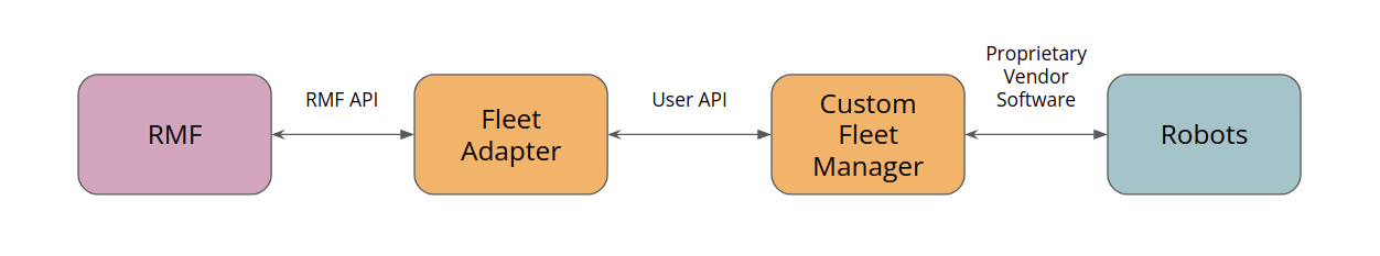
This fleet adapter system is also integrated in our demos worlds with simulation robots, which is further elaborated in the next section.
You can follow these steps to build your fleet adapter on top of the given template:
-
Fill in the missing code in
RobotClientAPI.py. With your chosen API (it could be ROS messages or any custom API), RMF will be able to command your robots and retrieve state updates. The crucial callbacks are:navigate(): Commands your robot to a target location given the coordinates[x, y, yaw].stop(): Commands your robot to stop in place.execute_action(): Triggers any custom action you would like your robot to perform when provided with acategoryanddescription, which detail the action name and task-specific parameters respectively. You may optionally want to make use ofRobotAPI.start_activityto trigger different types of actions for your robot.map(),position()andbattery_soc()each allows RMF to retrieve the relevant data from your robot. The robot state information helps RMF to allocate tasks, plan routes and initiate charging when needed.
-
For each robot fleet, create a
config.yamlfile to include important fleet parameters. These parameters will be passed to the fleet adapter and configured when initializing the fleet. Do note that you must list all robots in the fleet underrobotsto ensure that they are registered to the RMF fleet. -
[Optional] Create a fleet manager that interfaces with your fleet's robots if you'd like a consolidated manager for your fleet, rather than having RMF communicate with the individual robots. This fleet manager would be a bridge between the RMF fleet adapter and your fleet robots, as depicted in the diagram above. It should be able to relay navigation commands to the fleet robots and also report their robot statuses. If you have multiple fleets using different robot APIs, make sure to create separate fleet managers for these fleets.
If you have opted to use a fleet manager, you may find it helpful to include any relevant data in the fleet
config.yaml, demonstrated in thefleet_managersection here.
You may refer to the Fleet Adapter Tutorial section in this Book or rmf_demos RobotClientAPI for examples and in-depth step-by-step instructions.
Once you are done, you can run both the fleet adapter and any custom fleet manager. Remember to parse the configuration file and navigation graph when launching the adapter.
Case Study: RMF Demos Fleet Adapter
The Python implementation of the Full Control fleet adapter classes is demonstrated in the demos fleet adapter. Building on top of the fleet adapter template, the demos fleet adapter uses REST API as an interface between the adapter and the simulation robots: the adapter sends out commands to the robots, while the robots update the adapter on their current state information. This is done by creating a fleet_manager node that contains the necessary REST endpoints for RobotClientAPI to interact with.
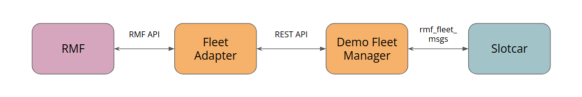
Demos Fleet Manager
Whenever a command is ready to be sent from the RMF fleet adapter, it will call the relevant API function defined in RobotClientAPI and query the corresponding endpoint from the API server in the fleet_manager node. Each function either retrieves specific information about the robot's current state (including but not limited to its last known position, remaining battery level, and whether it has completed a request), or sends a command to the robot to carry out a request. The robot state information is required for the fleet adapter to update the traffic schedule, plan for subsequent tasks, and guide robots across different paths in the environment.
The demos fleet adapter is integrated with the simulation robots which publish their state information via internal ROS2 messages, hence the fleet_manager also serves to consolidate the messages published by different robots from its fleet and sends them to the designated robot's fleet adapter. The API endpoints are designed such that the adapter can query information or send commands to a particular robot by specifying the robot's name. The fleet_manager will ensure that the robot exists in the fleet before returning the requested state information or relaying commands to the simulation robot. Additionally, the adapter can retrieve the status of the entire fleet's robots.
Fleet Configuration
There are four Full Control fleets in our demo simulation, each with their own fleet-specific parameters. To better consolidate and set up these configurations upon initializing the fleet, they are stored in a config.yaml file. Paths to the configuration and navigation graph files are required when running the fleet adapter and manager. General fleet settings and capabilities are defined under the rmf_fleet section.
The config file also takes care of robot-specific parameters within the fleet, such as the number of robots in the fleet, each of their names and their starting waypoints. For example, the tinyRobot fleet in Office demo world has two robots, so we append the configurations for each robot to the robots section in the config file.
For users who are operating their robots in a different coordinate frame from RMF, the reference_coordinate section in the config file helps to perform any necessary transformations. Do note that RMF and the slotcar simulation robots share the same coordinate frame, so this transformation is not implemented in the demos fleet adapter.
Fleet Adapter Tutorial (Python)
fleet_adapter acts as a bridge between the robots and the core RMF system.
Its responsibilities include but are not limited to:
-
Updating the traffic schedule with the fleet robot's positions
-
Responding to tasks
-
Controlling the vendor robots.
The fleet_adapter receives information (position, current ongoing tasks, battery levels etc.) about each robot in the fleet and sends them to the core RMF system for task planning and scheduling.
-
When the core RMF system has a task to dispatch, it communicates with the various fleet adapters to check which fleet is suitable for taking this task.
-
It sends a request, to which fleet adapters respond by submitting their fleet robots' availability and statuses.
-
RMF determines the best fleet for the task and responds to the winning bid, i.e. the fleet that is selected. The response contains navigation commands relevant to the delegated task.
-
The fleet adapter will then send the navigation commands to the robot in appropriate API.
The tutorial provided below is based on the rmf_demos_fleet_adapter implemented in the rmf_demos repository. This specific implementation is written in Python and uses REST API as an interface between the fleet adapter and fleet manager. You may choose to use other APIs for your own integration.
1. Pre-requisites
Fetch dependencies
Before running your fleet adapter, make sure that you have ROS 2 and RMF installed by following the instructions here. You have the option of installing the binaries or building from source for both. You may also wish to head over to our RMF Github repo for the latest updates and instructions for RMF installation.
If you built ROS 2 and/or RMF from source, make sure to source the workspace that contains their built code before proceeding to the next step.
In our example, the rmf_demos_fleet_adapter uses REST API as an interface between the fleet adapter and robot fleet manager, hence to get the demos working we will need to install the required dependencies to use FastAPI.
pip3 install fastapi uvicorn
This step is only required for this implementation; depending on what API your own fleet manager uses, you'll have to install any necessary dependencies accordingly.
Get started with the fleet adapter template
Create a workspace and clone the fleet_adapter_template repository.
mkdir -p ~/rmf_ws/src
cd ~/rmf_ws/src/
git clone https://github.com/open-rmf/fleet_adapter_template.git
This template contains the code for both Full Control and Easy Full Control fleet adapters. Both implementations use API calls in RobotClientAPI.py to communicate with the robots.
2. Update the config.yaml file
The config.yaml file contains important parameters for setting up the fleet adapter. Users should start by updating these configurations describing their fleet robots.
It is important to stick to the provided fields in the sample config.yaml below, otherwise there will be import errors when parsing this YAML file to the fleet adapter. If you would like to edit any of the field names or value range, or even append additional fields, please ensure that you also modify the part of your fleet adapter code that handles this configuration import accordingly.
Some fields are optional as indicated below.
# FLEET CONFIG =================================================================
# RMF Fleet parameters

rmf_fleet:
  name: "tinyRobot"
  limits:
    linear: [0.5, 0.75] # velocity, acceleration
    angular: [0.6, 2.0] # velocity, acceleration
  profile: # Robot profile is modelled as a circle
    footprint: 0.3 # radius in m
    vicinity: 0.5 # radius in m
  reversible: True # whether robots in this fleet can reverse
  battery_system:
    voltage: 12.0 # V
    capacity: 24.0 # Ahr
    charging_current: 5.0 # A
  mechanical_system:
    mass: 20.0 # kg
    moment_of_inertia: 10.0 #kgm^2
    friction_coefficient: 0.22
  ambient_system:
    power: 20.0 # W
  tool_system:
    power: 0.0 # W
  recharge_threshold: 0.10 # Battery level below which robots in this fleet will not operate
  recharge_soc: 1.0 # Battery level to which robots in this fleet should be charged up to during recharging tasks
  publish_fleet_state: 10.0 # Publish frequency for fleet state, ensure that it is same as robot_state_update_frequency
  account_for_battery_drain: True
  task_capabilities: # Specify the types of RMF Tasks that robots in this fleet are capable of performing
    loop: True
    delivery: True
  actions: ["teleop"]
  finishing_request: "park" # [park, charge, nothing]
  responsive_wait: True # Should responsive wait be on/off for the whole fleet by default? False if not specified.
  robots:
    tinyRobot1:
        charger: "tinyRobot1_charger"
        responsive_wait: False # Should responsive wait be on/off for this specific robot? Overrides the fleet-wide setting.
    tinyRobot2:
        charger: "tinyRobot2_charger"
        # No mention of responsive_wait means the fleet-wide setting will be used

  robot_state_update_frequency: 10.0 # Hz

fleet_manager:
  prefix: "http://127.0.0.1:8080"
  user: "some_user"
  password: "some_password"

# TRANSFORM CONFIG =============================================================
# For computing transforms between Robot and RMF coordinate systems

# Optional
reference_coordinates:
  L1:
    rmf: [[20.33, -3.156],
          [8.908, -2.57],
          [13.02, -3.601],
          [21.93, -4.124]]
    robot: [[59, 399],
          [57, 172],
          [68, 251],
          [75, 429]]
-
rmf_fleet: Important fleet parameters including vehicle traits, task capabilities and user information for connecting to the fleet manager.-
limits: Maximum values for linear and angular accelerations and velocities. -
profile: Radius of the footprint and personal vicinity of the vehicles in this fleet. -
reversible: A flag to enable/disable reverse traversal in the robot. -
battery_system: Information about the battery's voltage, capacity and charging current. -
recharge_threshold: Sets a value for minimum charge below which the robot must return to its charger. -
recharge_soc: The fraction of total battery capacity to which the robot should be charged. -
task_capabilities: The tasks that the robot can perform betweenloop,deliveryandclean. -
account_for_battery_drain: Whether RMF should consider the battery drain of the robots before dispatching tasks. -
action[Optional]: A list of custom performable actions for the fleet. -
finishing_request: What the robot should do when it finishes its task, can be set topark,chargeornothing. -
responsive_wait[Optional]: True # Should responsive wait be on/off for the whole fleet by default? False if not specified. -
robots: Information about each individual robot in the fleet. Each item in this section corresponds to the configuration for a single robot in the fleet. You may add more robots accordingly.-
tinyRobot1: Name of the robot.-
charger: Name of the robot's charging point. -
responsive_wait: Whether this specific robot should turn its responsive wait on/off. Overrides the fleet-wide setting.
-
-
-
robot_state_update_frequency: How frequently should the robots update the fleet.
-
-
fleet_manager: The prefix, user and password fields that can be configured to suit your chosen API. Do make sure to also edit the corresponding fields inRobotClientAPI.pyif you do modify them. These parameters will be used to set up connection with your fleet manager/robots. -
reference_coordinates[Optional]: If the fleet robots are not operating in the same coordinate system as RMF, you can provide two sets of (x, y) coordinates that correspond to the same locations in each system. This helps with estimating coordinate transformations from one frame to another. A minimum of 4 matching waypoints is recommended.Note: this is not being implemented in
rmf_demos_fleet_adapteras the demos robots and RMF are using the same coordinate system.
3. Create navigation graphs
A navigation graph is required to be parsed to the fleet adapter so that RMF can understand the robots' environment. They can be created using the RMF Traffic Editor and the building_map_generator nav CLI provided. Refer to the traffic editor repo's README for installation and map generation instructions.
You may also want to look through the Traffic Editor section of this Book for detailed information and instructions on creating your own digital maps.
You should now have a YAML file with information about the lanes and waypoints (among other information) that describe the paths your robot fleet can take.
4. Fill in your RobotAPI
RobotClientAPI.py provides a set of methods being used by the fleet adapter. These callbacks are triggered when RMF needs to send or retrieve information via the fleet adapter to/from the managed robots. To cater to the interface of your choice, you need to fill in the missing code blocks marked with # IMPLEMENT YOUR CODE HERE # within RobotAPI with logics to send or retrieve the corresponding information. For example, if your robot uses REST API to interface with the fleet adapter, you will need to make HTTP request calls to the appropriate endpoints within these functions.
You may refer to the RobotAPI class implementated for rmf_demos_fleet_adapter for examples of how these methods can be filled up.
navigate: Sends a navigation command to the robot API. It takes in the destination coordinates from RMF, desired map name and optional speed limit.start_activity: Sends a command to the robot to start performing a task. This method is helpful for custom performable actions that are triggered byexecute_action().stop: Commands the robot to stop moving.position,mapandbattery_soc: Retrieves the robot's current position in its coordinate frame in the format[x, y, theta], its current map name, and its battery state of charge. Inrmf_demos_fleet_adapterthese methods are consolidated underget_data().is_command_completed: Checks if the robot has completed the ongoing process or task. Inrmf_demos_fleet_adapter, this is implemented under theRobotUpdateDataclass. Depending on your robot API you may choose to integrate it either way. This callback will help RMF recognize when a dispatched command is completed, and proceed to send subsequent commands.
Further parameters may be added to RobotAPI to be used in these callbacks if required, such as authentication details and task IDs. You may also wish to write additional methods in either RobotAPI and fleet_adapter.py for specific use cases. The rmf_demos_fleet_adapter implementation demonstrates this for a Teleoperation action, which will be elaborated more in the PerformAction tutorial.
5. Create your fleet adapter!
Now that we have our components ready, we can start creating our fleet adapter. fleet_adapter.py uses the Easy Full Control API to easily create an Adapter instance and set up the fleet configurations and robots by parsing the configuration YAML file that we have prepared previously. Since we have defined our RobotAPI, the methods implemented will be used by the callbacks in fleet_adapter.py so that RMF can retrieve robot information and send out navigation or action commands appropriately.
You may wish to use the fleet_adapter.py available from the fleet adapter template and modify it according to what you'd like your fleet to achieve.
6. Run your fleet adapter
At this point, you should have 4 components ready in order to run your fleet adapter:
fleet_adapter.pyRobotClientAPI.py- Fleet
config.yamlfile - Navigation graph
Build your fleet adapter package
If you cloned the fleet_adapter_template repository, you would already have your Python scripts in a ROS 2 package. Otherwise, you can follow the instructions here to create a package in your workspace. For the instructions below, we will use the package and module names used in the fleet_adapter_template package.
With your scripts in the appropriate folder, go back to the root directory of your workspace and build the package.
colcon build --packages-select fleet_adapter_template
Run!
We will now source our workspace and run the fleet adapter:
. ~/rmf_ws/install/setup.bash

ros2 run fleet_adapter_template fleet_adapter -c <path-to-config> -n <path-to-nav-graph>
7. Deep dive into the code [Optional]
The following steps elaborate on the Easy Full Control fleet adapter and what each part of the code does.
a. Import important parameters and create an Adapter
When running our fleet adapter, we will need to parse in the fleet config file and navigation graphs that we created in earlier steps. These files will be passed to the EasyFullControl API to set up fleet configurations for the adapter.
    config_path = args.config_file
    nav_graph_path = args.nav_graph

    fleet_config = rmf_easy.FleetConfiguration.from_config_files(
        config_path, nav_graph_path
    )
    assert fleet_config, f'Failed to parse config file [{config_path}]'

    # Parse the yaml in Python to get the fleet_manager info
    with open(config_path, "r") as f:
        config_yaml = yaml.safe_load(f)
With these parameters, we can create an Adapter instance and add an EasyFullControl fleet to it. We would also want to configure the use_sim_time and server_uri parameters if the adapter should operate according to simulation clock or broadcast task updates to any websocket servers.
    # ROS 2 node for the command handle
    fleet_name = fleet_config.fleet_name
    node = rclpy.node.Node(f'{fleet_name}_command_handle')
    adapter = Adapter.make(f'{fleet_name}_fleet_adapter')
    assert adapter, (
        'Unable to initialize fleet adapter. '
        'Please ensure RMF Schedule Node is running'
    )

    # Enable sim time for testing offline
    if args.use_sim_time:
        param = Parameter("use_sim_time", Parameter.Type.BOOL, True)
        node.set_parameters([param])
        adapter.node.use_sim_time()

    adapter.start()
    time.sleep(1.0)

    if args.server_uri == '':
        server_uri = None
    else:
        server_uri = args.server_uri

    fleet_config.server_uri = server_uri
    fleet_handle = adapter.add_easy_fleet(fleet_config)
b. Configure transformations between RMF and robot
We have defined a helper function to compute the transforms between RMF and the robot's coordinates. In the event your robot operates in the same coordinates as RMF (e.g. in simulation), you won't need this portion of the code.
def compute_transforms(level, coords, node=None):
    """Get transforms between RMF and robot coordinates."""
    rmf_coords = coords['rmf']
    robot_coords = coords['robot']
    tf = nudged.estimate(rmf_coords, robot_coords)
    if node:
        mse = nudged.estimate_error(tf, rmf_coords, robot_coords)
        node.get_logger().info(
            f"Transformation error estimate for {level}: {mse}"
        )

    return Transformation(
        tf.get_rotation(),
        tf.get_scale(),
        tf.get_translation()
    )
    # Configure the transforms between robot and RMF frames
    for level, coords in config_yaml['reference_coordinates'].items():
        tf = compute_transforms(level, coords, node)
        fleet_config.add_robot_coordinates_transformation(level, tf)
Depending on the number of maps (or levels) required for your integration, you will extract the corresponding coordinate transformations for each map and add them to the FleetConfiguration object. The transformation error estimate will be logged by this function if you pass your rclpy.Node into it.
Then, in our main function, we add the computed transforms to our FleetConfiguration. The EasyFullControl fleet adapter will process these transforms and send out navigation commands in the robot's coordinates accordingly.
    # Configure the transforms between robot and RMF frames
    for level, coords in config_yaml['reference_coordinates'].items():
        tf = compute_transforms(level, coords, node)
        fleet_config.add_robot_coordinates_transformation(level, tf)
c. Initialize the robot API and set up RobotAdapter
The config.yaml may include any connection credentials we'd need to connect to our robot or robot fleet manager. We parse this to the RobotAPI to easily interact between RMF and the robot's API. This is entirely optional; for more secure storage of credentials, do import them into RobotAPI accordingly.
    # Initialize robot API for this fleet
    fleet_mgr_yaml = config_yaml['fleet_manager']
    api = RobotAPI(fleet_mgr_yaml)
Given a list of known robots from our config.yaml, we can initialize a RobotAdapter class for each robot that is supposed to be added to the fleet.
    robots = {}
    for robot_name in fleet_config.known_robots:
        robot_config = fleet_config.get_known_robot_configuration(robot_name)
        robots[robot_name] = RobotAdapter(
            robot_name, robot_config, node, api, fleet_handle
        )
d. Retrieve robot status and add robot to the fleet
This update loop will allow us to update the RobotUpdateHandle with our robots' information asynchronously, such that any error in retrieving the status from one robot won't block the other robots from updating the fleet adapter.
    update_period = 1.0/config_yaml['rmf_fleet'].get(
        'robot_state_update_frequency', 10.0
    )

    def update_loop():
        asyncio.set_event_loop(asyncio.new_event_loop())
        while rclpy.ok():
            now = node.get_clock().now()

            # Update all the robots in parallel using a thread pool
            update_jobs = []
            for robot in robots.keys():
                update_jobs.append(update_robot(robot))

            asyncio.get_event_loop().run_until_complete(
                asyncio.wait(update_jobs)
            )

            next_wakeup = now + Duration(nanoseconds=update_period*1e9)
            while node.get_clock().now() < next_wakeup:
                time.sleep(0.001)

    update_thread = threading.Thread(target=update_loop, args=())
    update_thread.start()
The function update_robot() is called to ensure that our robots' current map, position and battery state of charge will be updated properly. If the robot is new to the fleet handle, we will add it in via add_robot().
@parallel
def update_robot(robot: RobotAdapter):
    data = robot.api.get_data(robot.name)
    if data is None:
        return

    state = rmf_easy.RobotState(
        data.map,
        data.position,
        data.battery_soc
    )

    if robot.update_handle is None:
        robot.update_handle = robot.fleet_handle.add_robot(
            robot.name,
            state,
            robot.configuration,
            robot.make_callbacks()
        )
        return

    robot.update(state)
e. Inside the RobotAdapter class
The RobotAdapter class helps us to keep track of any ongoing process the robot may be carrying out, and perform the correct actions when RMFs sends a corresponding command.
class RobotAdapter:
    def __init__(
        self,
        name: str,
        configuration,
        node,
        api: RobotAPI,
        fleet_handle
    ):
        self.name = name
        self.execution = None
        self.update_handle = None
        self.configuration = configuration
        self.node = node
        self.api = api
        self.fleet_handle = fleet_handle
There are 3 important callbacks that we need to pass on to the EasyFullControl API:
navigatestopexecute_action
As described above, each of these callbacks will be triggered by RMF when it needs to command to robot to do something. Hence, we define these callbacks in our RobotAdapter:
    def navigate(self, destination, execution):
        self.execution = execution
        self.node.get_logger().info(
            f'Commanding [{self.name}] to navigate to {destination.position} '
            f'on map [{destination.map}]'
        )

        self.api.navigate(
            self.name,
            destination.position,
            destination.map,
            destination.speed_limit
        )

    def stop(self, activity):
        if self.execution is not None:
            if self.execution.identifier.is_same(activity):
                self.execution = None
                self.stop(self.name)

    def execute_action(self, category: str, description: dict, execution):
        ''' Trigger a custom action you would like your robot to perform.
        You may wish to use RobotAPI.start_activity to trigger different
        types of actions to your robot.'''
        self.execution = execution
        # ------------------------ #
        # IMPLEMENT YOUR CODE HERE #
        # ------------------------ #
        return
Notice that execute_action(~) does not have any implemented code in the fleet adapter template. This callback is designed to be flexible and caters to custom performable actions that may not be availble under the tasks offered in RMF. You can learn how to design and compose your own actions and execute them from the fleet adapter in the PerformAction tutorial section.
    def make_callbacks(self):
        return rmf_easy.RobotCallbacks(
            lambda destination, execution: self.navigate(
                destination, execution
            ),
            lambda activity: self.stop(activity),
            lambda category, description, execution: self.execute_action(
                category, description, execution
            )
        )
Finally, we add all of our callbacks to our fleet adapter using the RobotCallbacks() API.
PerformAction Tutorial (Python)
This tutorial is an extension of the Fleet Adapter Tutorial and will guide you to write custom actions in your fleet adapter. While RMF offers a few standard tasks, we understand that different robots may be equipped and programmed to perform different types of actions, such as cleaning, object-picking, teleoperation, and so on. By supporting custom tasks, users can trigger a custom action specified in the fleet adapter's config.yaml beforehand, and RMF would relinquish control of the robot until it is signalled that the robot has completed the custom action. You may explore the Supporting a new Task in RMF section to read more about supporting custom tasks and how you can create your own task JSON to be sent to RMF.
In this tutorial, we will refer to a simplified version of the rmf_demos_fleet_adapter to implement a Clean PerformAction capability in our fleet adapter.
1. Define the PerformAction in the fleet config.yaml
We will need to define the name of the action in the fleet configuration, so that RMF recognizes this action as performable when a task is submitted and is able to dispatch it to a fleet that can fulfil it. In our config.yaml under the rmf_fleet section, we can provide a list of performable actions for our fleet. For example, let's define clean as an action supported by this fleet:
rmf_fleet:
  actions: ["clean"]
2. Apply action execution logic inside our fleet adapter
After RMF receives a task consisting of this action and dispatches it to the right fleet, the fleet adapter's execute_action(~) callback will be triggered. The category parsed to this callback corresponds to the action name that we have previously defined, and the description consists of any details about the action that we might be interested in.
Assume that this is the task JSON submitted to RMF:
{
  "type": "dispatch_task_request",
  "request": {
    "unix_millis_earliest_start_time": start_time,
    "category": "clean",
    "description": {
      "zone": "clean_lobby"
    }
  }
}
In our example, the category provided would be clean, and the description would contain which cleaning zone this task is directing our robot to, which is clean_lobby. Hence, we will need to implement the logic in our execute_action(~):
    def execute_action(self, category: str, description: dict, execution):
        self.execution = execution

        if category == 'clean':
            self.perform_clean(description['zone'])

    def perform_clean(self, zone):
        if self.api.start_activity(self.name, 'clean', zone):
            self.node.get_logger().info(
                f'Commanding [{self.name}] to clean zone [{zone}]'
            )
        else:
            self.node.get_logger().error(
                f'Fleet manager for [{self.name}] does not know how to '
                f'clean zone [{zone}]. We will terminate the activity.'
            )
            self.execution.finished()
            self.execution = None
Since our fleet may be capable of performing multiple custom actions, we will need to conduct a check to ensure that the category received matches the robot API that we are targeting. Upon receiving a clean action, we can trigger the robot's API accordingly.
3. Implement the robot API for the custom action
This is where the start_activity(~) method inside RobotClientAPI.py comes into play. We would require it to implement the API call to the robot to start the cleaning activity. As an example, if the robot API uses REST to make calls to the robot, the implemented method may look like this:
    def start_activity(
        self,
        robot_name: str,
        activity: str,
        label: str
    ):
        ''' Request the robot to begin a process. This is specific to the robot
            and the use case. For example, load/unload a cart for Deliverybot
            or begin cleaning a zone for a cleaning robot.'''
        url = (
            self.prefix +
            f"/open-rmf/rmf_demos_fm/start_activity?robot_name={robot_name}"
        )
        # data fields: task, map_name, destination{}, data{}
        data = {'activity': activity, 'label': label}
        try:
            response = requests.post(url, timeout=self.timeout, json=data)
            response.raise_for_status()
            if self.debug:
                print(f'Response: {response.json()}')

            if response.json()['success']:
                return True

            # If we get a response with success=False, then
            return False
        except HTTPError as http_err:
            print(f'HTTP error for {robot_name} in start_activity: {http_err}')
        except Exception as err:
            print(f'Other error {robot_name} in start_activity: {err}')
        return False
4. Complete the action
Since we stored a self.execution object in our RobotAdapter, we will be notified when any execution (navigation, stop, or action) is completed as the update loop continually calls is_command_completed to check on its status.
    def update(self, state):
        activity_identifier = None
        if self.execution:
            if self.api.is_command_completed():
                self.execution.finished()
                self.execution = None
            else:
                activity_identifier = self.execution.identifier
If your implementation requires a separate callback to mark the execution as finished, you can create a new function to conduct this check and call self.execution.finished() when the action is completed.
Free Fleet Adapter
The free fleet adapter formerly known as Free Fleet, allows users to integrate standalone mobile robots to form a heterogeneous fleet, to work with Open-RMF.
The free_fleet_adapter implements the Easy Full Control fleet adapter API, and communicates with individual robots over Zenoh bridges. Out-of-the-box, it supports robots running ROS 1 Navigation as well as ROS 2 Navigation2.
Check out the simulation examples for more information.
Below is the ideal integration architecture of several robots that are running either ROS 2 Navigation2 or ROS 1 Navigation.
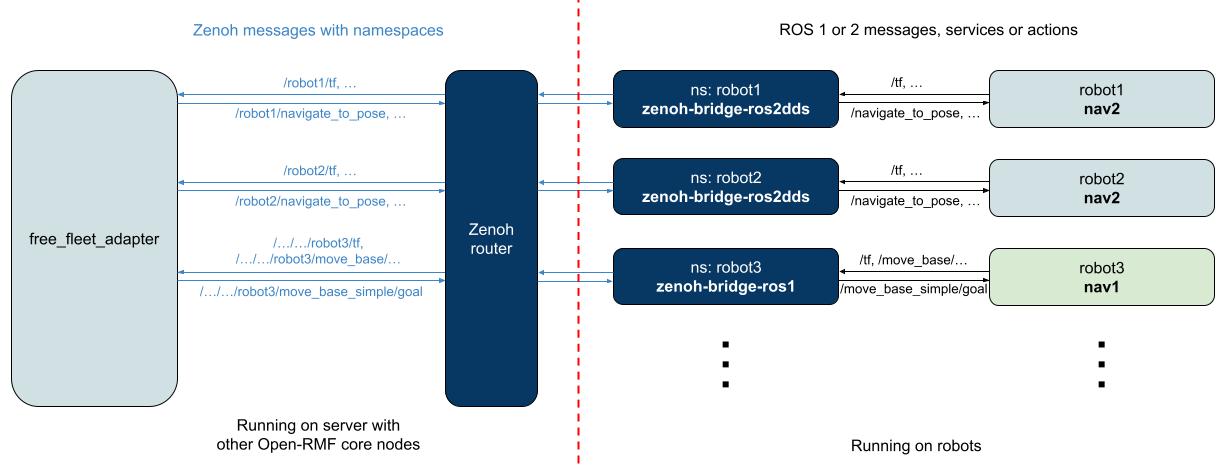
With Zenoh bridges, users should be able to integrate their robot as-is, without additional namespacing. The Zenoh bridges are responsible for filtering topics to reduce network traffic, and to namespace the various Zenoh keys, which the free_fleet_adapter operates on. Handling message definitions across domains have been greatly simplified too, thanks to pycdr2 for ROS 2 messages and rosbags for ROS 1 messages.
ROS 2 Navigation2
For ROS 2 Navigation2, the integration is enabled by zenoh-bridge-ros2dds. With an appropriately configured bridge running on the robot, the free_fleet_adapter is able to communicate and control the robot, via its navigation behavior trees.


The Navigation2 integration currently uses the simple navigate_to_pose behavior to provide navigation commands from point to point following the RMF waypoints defined. Support for utilizing more Navigation2 behaviors or custom behaviors is on the roadmap, but in the meantime, contributions are always welcome!
Below is an example of the robot defined in the fleet configuration file, you can find the file here. Take note of the defined navigation_stack, this allows the free_fleet_adapter to pick the Nav2RobotAdapter for this particular robot.
...
  robots:
    nav2_tb3:
      charger: "tb3_charger"
      responsive_wait: False # Should responsive wait be on/off for this specific robot? Overrides the fleet-wide setting.
      # For Nav2RobotAdapter
      navigation_stack: 2
      initial_map: "L1"
      maps:
        L1:
          map_url: "/opt/ros/jazzy/share/nav2_bringup/maps/tb3_sandbox.yaml"
,,,
Below is an example of the Zenoh configuration file used by the zenoh-bridge-ros2dds on the robot. The Zenoh keys are namespaced by the namespace parameter, while we are able to filter and rate-limit ROS 2 topics, services, actions to reduce network traffic. With the client mode, the bridge will seek to connect to a locally available Zenoh router.
{
  plugins: {
    ros2dds: {
      namespace: "/nav2_tb3",
      allow: {
        publishers: [".*/tf", ".*/battery_state"],
        subscribers: [],
        service_servers: [],
        service_clients: [],
        action_servers: [".*/navigate_to_pose"],
        action_clients: [],
      },
      pub_max_frequencies: [".*/navigate_to_pose/*=1", ".*/battery_state=1"],
    },
  },
  // Zenoh related configurations
  mode: "client",
  connect: {
    endpoints: []
  },
  listen: {
    endpoints: []
  },
}
Check out our integration test setup to get a better idea on how this integration can be deployed.
ROS 1 Navigation Stack
The ROS 1 Navigation integration has only been tested in simulation and in ROS 1 Noetic, and is currently still using a fork of zenoh-plugin-ros1, to support bridge namespacing. This will be updated after contributions to upstream has been made.
For ROS 1 Navigation, the integration is enabled by zenoh-bridge-ros1. Similarly, with an appropriately configured bridge running on the robot, the free_fleet_adapter is able to communicate and control the robot, via the move_base topics.

Below is an example of the robot defined in the fleet configuration file, you can find the file here. Take note of the defined navigation_stack, this allows the free_fleet_adapter to pick the Nav1RobotAdapter for this particular robot.
...
  robots:
    nav1_tb3:
      charger: "tb3_charger"
      responsive_wait: False # Should responsive wait be on/off for this specific robot? Overrides the fleet-wide setting.
      # For Nav1RobotAdapter
      navigation_stack: 1
      initial_map: "L1"
      maps:
        L1:
          # The nav1 robot will generally no access to this nav2_bringup package, this should point to where the nav1 map is stored.
          map_url: "/tmp/navigation2/nav2_bringup/maps/tb3_sandbox.yaml"
,,,
Below is an example of the Zenoh configuration file used by the zenoh-bridge-ros1 on the robot. The Zenoh keys are namespaced by the bridge_namespace parameter, while we are able to filter ROS 1 topics and services to reduce network traffic. With the client mode, the bridge will seek to connect to a locally available Zenoh router.
{
  plugins: {
    ros1: {
      bridge_namespace: "nav1_tb3",
      subscriber_bridging_mode: "disabled",
      publisher_bridging_mode: "disabled",
      service_bridging_mode: "disabled",
      client_bridging_mode: "disabled",
      // Zenoh -> ROS 1
      subscriber_topic_custom_bridging_mode: {
        "/move_base_simple/goal": "auto",
        "/move_base/cancel": "auto",
      },
      // ROS 1 -> Zenoh
      publisher_topic_custom_bridging_mode: {
        "/tf": "auto",
        "/battery_state": "auto",
        "/move_base/status": "auto"
      },
    },
  },
  // Zenoh related configurations
  mode: "client",
  connect: {
    endpoints: []
  },
  listen: {
    endpoints: []
  },
}
Check out our integration test setup to get a better idea on how this integration can be deployed.
Custom Navigation Stack
Users looking to integrate their own custom navigation stack, can implement the abstract interfaces in RobotAdapter here.
The implementation will need a name, for the free_fleet_adapter to correctly allocate adapters to each connected robot. This name is configured in the robot's configuration in the fleet configuration file. For example, Navigation2 is just 2, while ROS 1 Navigation is 1.
Contributions are always welcome!
More information and links
- Repository
- Free fleet legacy implementation and documentation page.
- zenoh-bridge-ros2dds
- Custom zenoh-bridge-ros1 fork
Legacy - Free Fleet
In the event that the user wishes to integrate a standalone mobile robot which doesn't come with its own fleet management system, the open source fleet management system free_fleet could be used.
The free_fleet system is split into a client and a server. The client is to be run on each of these standalone mobile robots alongside their navigation software and is intended to have direct control over the mobile robot while at the same time monitor its status and report back to the server. The client's base implementation is designed to allow interaction with different configurations of mobile robots yet report to the same server. This way, users are able to use free_fleet to manage a heterogeneous fleet of robots, each using different distributions of ROS, versions of ROS, navigation software, or onboard communication protocols.
The server is run on a central computer and consolidates the incoming status updates from each client to be either visualized using a UI, or relayed upstream to RMF. The server also relays commands from the user via the UI or from RMF down to the clients to be executed. Each server can work with multiple clients at a time, hence it serves the role of a fleet management system. The server can be implemented and used as its own fleet management system or work with larger systems like RMF, bridging the gap between each mobile robot's API and RMF's API and interface.
The communication between the free_fleet server and free_fleet clients is implemented using CycloneDDS, therefore we are not concerned if the mobile robot or central computer is running different versions of ROS.
In this section, we will address 4 different approaches of using free_fleet to integrate with RMF, specifically the navigation stack used by the robot. Each approach maintains a similar systems architecture, which is illustrated in the simple block diagram below, but there are specific examples depending on the software choice for the navigation stack used by the robot developer.
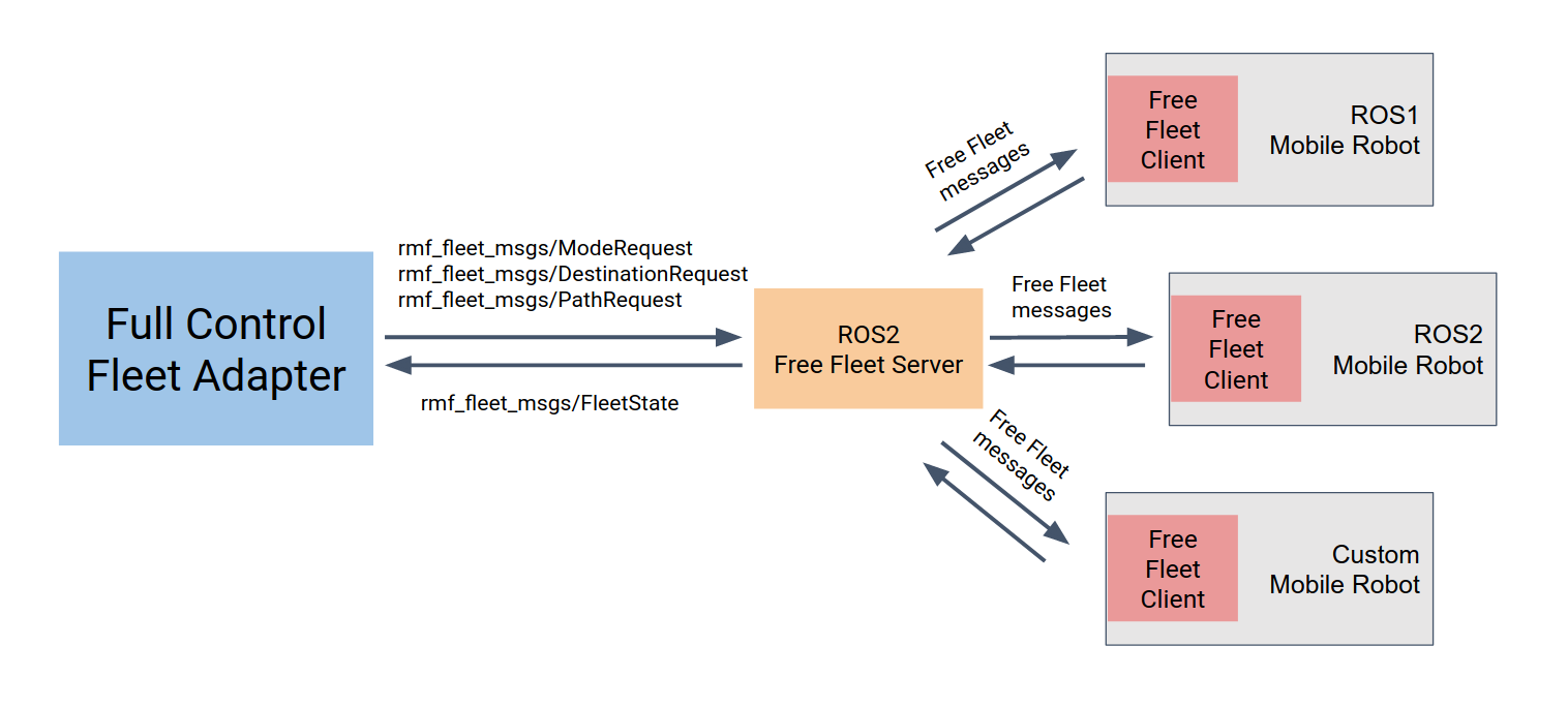
ROS 1 Navigation Stack
An implementation of a free_fleet client that works with a ROS 1 navigation stack can be found in the free_fleet repository. The implementation expects the transforms of the mobile robot to be fully defined, the mobile robot to accept navigation commands via the move_base action library, as well as publishing its battery status published using the sensor_msgs/BatteryState message.
After following the build instructions on the README on the mobile robot, the user can launch the client as part of their launch script while at the same time define the necessary parameters using rosparam. Below is a small snippet example of how a client can be launched, with its paramters defined,
<node name="free_fleet_client_node"
    pkg="free_fleet_client_ros1"
    type="free_fleet_client_ros1" output="screen">

  <!-- These parameters will be used to identify the mobile robots -->
  <param name="fleet_name" type="string" value="example_fleet"/>
  <param name="robot_name" type="string" value="example_bot"/>
  <param name="robot_model" type="string" value="Turtlebot3"/>

  <!-- These are the topics required to get battery and level information -->
  <param name="battery_state_topic" type="string" value="example_bot/battery_state"/>
  <param name="level_name_topic" type="string" value="example_bot/level_name"/>

  <!-- These frames will be used to update the mobile robot's location -->
  <param name="map_frame" type="string" value="example_bot/map"/>
  <param name="robot_frame" type="string" value="example_bot/base_footprint"/>

  <!-- The name of the move_base server for actions -->
  <param name="move_base_server_name" type="string" value="example_bot/move_base"/>

  <!-- These are DDS configurations used between Free Fleet clients and servers -->
  <param name="dds_domain" type="int" value="42"/>
  <param name="dds_state_topic" type="string" value="robot_state"/>
  <param name="dds_mode_request_topic" type="string" value="mode_request"/>
  <param name="dds_path_request_topic" type="string" value="path_request"/>
  <param name="dds_destination_request_topic" type="string" value="destination_request"/>

  <!-- This decides how long the client should wait for a valid transform and action server before failing -->
  <param name="wait_timeout" type="double" value="10"/>

  <!-- These define the frequency at which the client checks for commands and
  publishes the robot state to the server -->
  <param name="update_frequency" type="double" value="10.0"/>
  <param name="publish_frequency" type="double" value="1.0"/>

  <!-- The client will only pass on navigation commands if the destination or first waypoint
  of the path is within this distance away, otherwise it will ignore the command -->
  <param name="max_dist_to_first_waypoint" type="double" value="10.0"/>

</node>
The running free_fleet client will communicate with the nodes running on the robot via ROS 1, while publishing its state and subscribing to requests over DDS with the free_fleet server.
The current implementation of the free_fleet server is implemented with ROS 2 and communicates with RMF using the aforementioned ROS 2 message and topic interfaces of an RMF fleet adapter. The ROS 2 build instructions can also be found on the same repository. Similar to the client, a simple ROS 2 wrapper has been implemented, and it can be started using a .launch.xml file like so:
<node pkg="free_fleet_server_ros2"
    exec="free_fleet_server_ros2"
    name="free_fleet_server_node"
    node-name="free_fleet_server_node"
    output="both">

  <!-- Fleet name will be used to identify robots -->
  <param name="fleet_name" value="example_fleet"/>

  <!-- These are the ROS2 topic names that will be used to communicate with RMF -->
  <param name="fleet_state_topic" value="fleet_states"/>
  <param name="mode_request_topic" value="robot_mode_requests"/>
  <param name="path_request_topic" value="robot_path_requests"/>
  <param name="destination_request_topic" value="robot_destination_requests"/>

  <!-- These are the DDS specific configurations used to communicate with the clients -->
  <param name="dds_domain" value="42"/>
  <param name="dds_robot_state_topic" value="robot_state"/>
  <param name="dds_mode_request_topic" value="mode_request"/>
  <param name="dds_path_request_topic" value="path_request"/>
  <param name="dds_destination_request_topic" value="destination_request"/>

  <!-- This determines the frequency it checks for incoming state and request messages,
  as well as how often it publishes its fleet state to RMF -->
  <param name="update_state_frequency" value="20.0"/>
  <param name="publish_state_frequency" value="2.0"/>

  <!-- These transformations are required when the frame of the robot fleet is
  different from that of RMF globally. In order to transform a pose from the RMF
  frame to the free fleet robot frame, it is first scaled, rotated, then
  translated using these parameters -->
  <param name="scale" value="0.928"/>
  <param name="rotation" value="-0.013"/>
  <param name="translation_x" value="-4.117"/>
  <param name="translation_y" value="27.26"/>

</node>
Furthermore, an example of this configuration can be found in the repository as well, under the packages ff_examples_ros1 and ff_exmaples_ros2. This example launches the example simulation from ROBOTIS, which has a small simulated world with 3 Turtlebot3 mobile robots, each running its own ROS 1 navigation stack.
After successful builds for both ROS 1 and ROS 2 workspaces, the simulation can be launched following these instructions, which also includes a ROS 2 free_fleet server, publishing fleet state messages and accepting mode and navigation requests over ROS 2 messages and topics.
ROS 2 Navigation Stack
An implementation for a robot using ROS 2 would be similar to a ROS 1 navigation stack described earlier. At this time, the ROS 2 free_fleet client is still under development. This section will be updated once the refactoring, implementation and testing has been completed.
The same ready free_fleet server implementation in the repository will work in this scenario, as the interfaces provided by the fleet adapters are still the same ROS 2 messages and topics.
If required in the meantime, users can implement their own free_fleet client, by working with the free_fleet library that contains the base implementation and API for the DDS communication. This will be further elaborated in the next section, Developer Navigation Stack.
Developer Navigation Stack
In this implementation, it is assumed that the software running on the mobile robot was written by the robot developers themselves (or their immediate subcontractors) and the developers fully understand and have access to their robot's internal control software, API's and interfaces. This level of understanding and access will be necessary for implementing your own free_fleet client wrapper. The block diagram below illustrates this configuration:
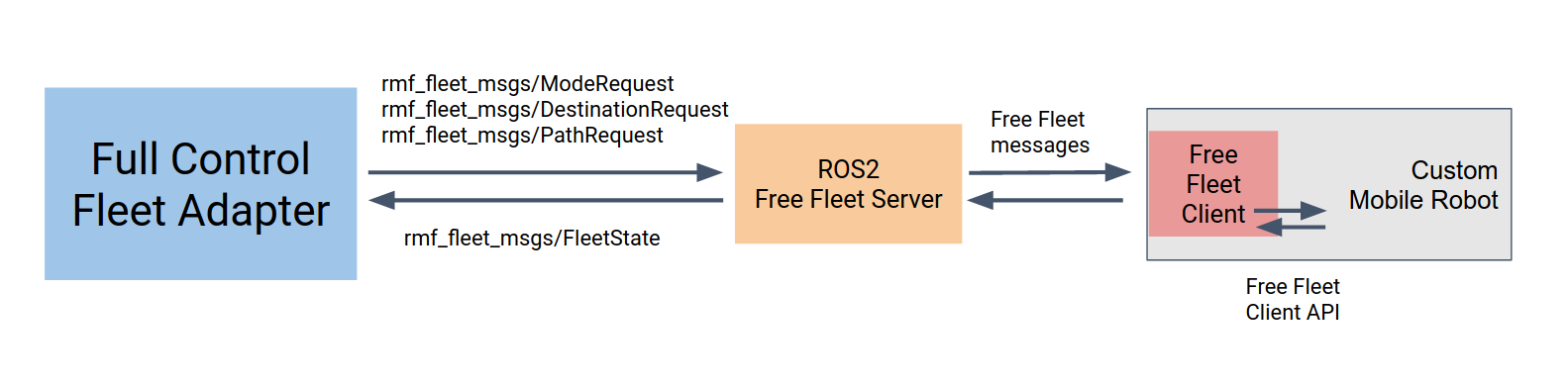
Once the developer's free_fleet client is fully functional, it will be a simple task of launching the same ROS 2 free_fleet server as mentioned earlier in this section to work with the fleet adapters through ROS 2 messages and topics.
Read-only Fleet Integration
In this section, we will cover the prototype API for integrating the Read Only category of mobile robot fleets. This means we assume the mobile robot fleet manager only allows RMF to see updates about where its robots are located and where they intend to go, but it does not offer any control over where the robots are going or how they can move around. This type of adapter is primarily aimed at legacy systems that were developed before RMF and did not anticipate the possibility of a third-party being able to command the robots.
Fleet Driver API
The Fleet Driver API was an experimental API developed in the early stages of the RMF research project. It can still be used for a read-only fleet adapter implementation until an officially supported C++ API comes out to replace it.
The Fleet Driver API uses ROS 2 messages from the rmf_fleet_msgs package. To use this API, you will want to write a ROS 2 application (using either rclcpp or rclpy) which we will refer to as the Fleet Driver. The job of the Fleet Driver is to transmit rmf_fleet_msgs/FleetState messages out to the fleet_states topic.
Inside the FleetState message is the name field. Be sure to fill in the correct name for your fleet state. There is also a collection of rmf_fleet_msgs/RobotState messages. For integrating a read-only fleet with RMF, the most crucial fields of the RobotState message are:
name- The name of the robot whose state is being specified.location- The current location of the robot.path- The sequence of locations that the robot will be traveling through.
Inside the rmf_fleet_msgs/Location message, the t field (which represents time) is generally ignored by the read-only fleet adapter. We assume that it is too cumbersome for your Fleet Driver to make timing predictions, so we have the read-only fleet adapter make the predictions for you based on the traits of the vehicle.
Configuring the Read Only Fleet Adapter
For the prototype read-only integration, there are two applications that need to be launched:
- The Fleet Driver mentioned above which you write specifically for your fleet's custom API
- The
read_onlyfleet adapter which must be launched through ROS 2
To launch the fleet adapter, you will need to use ros2 launch and include rmf_fleet_adapter/fleet_adapter.launch.xml file with the required parameters filled in. An example of this using the XML front-end of ros2 launch can be found in rmf_demos, copied below:
<?xml version='1.0' ?>

<launch>

  <arg name="fleet_name" default="caddy" description="Name of this fleet of caddy robots"/>

  <group>
    <include file="$(find-pkg-share rmf_fleet_adapter)/fleet_adapter.launch.xml">

      <!-- The name and control type of the fleet -->
      <arg name="fleet_name" value="$(var fleet_name)"/>
      <arg name="control_type" value="read_only"/>

      <!-- The nominal linear and angular velocity of the caddy -->
      <arg name="linear_velocity" value="1.0"/>
      <arg name="angular_velocity" value="0.6"/>

      <!-- The nominal linear and angular acceleration of the caddy -->
      <arg name="linear_acceleration" value="0.7"/>
      <arg name="angular_acceleration" value="1.5"/>

      <!-- The radius of the circular footprint of the caddy -->
      <arg name="footprint_radius" value="1.5"/>
      <!-- Other robots are not allowed within this radius -->
      <arg name="vicinity_radius" value="5.0"/>

      <arg name="delay_threshold" value="1.0"/>

    </include>
  </group>
The critical parameters are:
fleet_name: This must match thenamevalue that the Fleet Driver gives to itsFleetStatemessages.control_type: This must be"read_only".linear_velocity,angular_velocity,linear_acceleration, andangular_acceleration: These are estimates of the kinematic properties of the vehicles. For the sake of effective scheduling, it is preferable to overestimate these values than underestimate them, so it is best to think of these parameters as upper bounds for the values.footprint_radius: The radius of physical space that the vehicle occupies. This should cover the maximum extent of the physical footprint.vicinity_radius: The radius around the robot in which other robots are forbidden to physically enter. It is assumed that another robot entering this radius will interfere with the ability of this robot to operate.
When the launch file and Fleet Driver application are both ready, you can launch them side-by-side and the integration of the read-only fleet adapter will be complete.
Doors
Map Requirements
Before a door can be properly integrated, be sure to draw up the door locations with the correct door names on the navigation graph using traffic_editor. The instructions to do so can be found in the Traffic Editor chapter.
Integration
Door integration is required when integrating RMF into a new environment. For hopefully obvious reasons, only automated doors can be integrated with RMF though it may be possible to trigger an alert to a designated human to open a manual door but this is not recommended. An automated door can be defined as an electronically powered door that is remotely controllable, either using a remote trigger or has been outfitted with a computing unit capable of commanding the door to open and close when needed, using certain interfaces.
Doors can be integrated with RMF using a ROS 2 door node and a door adapter, which we sometimes refer to as a door supervisor. The block diagram below displays the relationship and communication modes between each component:
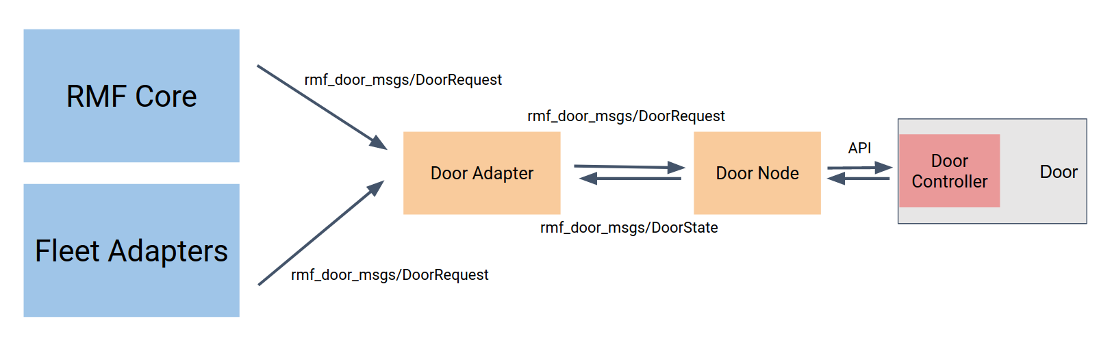
The door node will have to be implemented based on the make and model of the door that is being integrated in order to address the specific API of the door controller module. The communication protocol will also be dependent on the door and controller model, which might be some form of REST, RPCXML, etc. The door node is in charge of publishing its state and receiving commands over ROS 2, using the messages and topics listed below:
| Message Types | ROS2 Topic | Description |
|---|---|---|
rmf_door_msgs/DoorState | /door_states | State of the door published by the door node |
rmf_door_msgs/DoorRequest | /door_requests | Direct requests subscribed by the door node and published by the door adapter |
rmf_door_msgs/DoorRequest | /adapter_door_requests | Requests to be sent to the door adapter/supervisor to request safe operation of doors |
The door adapter stands in between the rest of the RMF core systems, fleet adapters, and the door node, and acts like a state supervisor ensuring that the doors are not acting on requests that might obstruct an ongoing mobile robot task or accidentally closing on it. It keeps track of the door state from the door node, and receives requests from the adapter_door_requests topic which are published by either fleet adapters or other parts of the RMF core system. Only when the door adapter deems that a request is safe enough to be performed, it will instruct the door node using a request. It should also be noted that direct requests sent to the door node, without going through the door adapter will be negated by the door adapter, to return it to its prior state in order to prevent disruptions during operations with mobile robots.
Door Adapter Template
To make the process of integrating doors with RMF even simpler, we have open-sourced a template package where users only need to update certain blocks of code with the API calls to their specific door controller.
Lifts (i.e. Elevators)
Map requirements
Before a lift can be properly integrated, be sure to draw up the lift locations with the correct lift names and levels on the navigation graph using traffic_editor. The instructions to do so can be found in Traffic Editor chapter.
Integration
Elevator integration will allow RMF to work over multiple levels, resolving conflicts and managing shared resources on a larger scale. Similar to door integration, the basic requirement is that the lift controller accepts commands using a prescribed protocol, OPC is one such example.
The elevators will be integrated in a similar fashion as doors as well, relying on a lift node and a lift adapter. The following block diagram shows how each component works with each other:
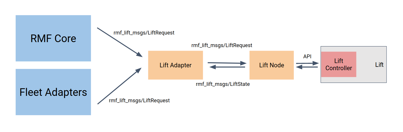
The lift node will act as a driver to work with the lift controller. An example of a lift node can be found in this repository. The node will publish its state and receive lift requests over ROS 2, using the messages and topics listed below.
| Message Types | ROS2 Topic | Description |
|---|---|---|
rmf_lift_msgs/LiftState | /lift_states | State of the lift published by the lift node |
rmf_lift_msgs/LiftRequest | /lift_requests | Direct requests subscribed by the lift node and published by the lift adapter |
rmf_lift_msgs/LiftRequest | /adapter_lift_requests | Requests to be sent to the lift adapter/supervisor to request safe operation of lifts |
A lift adapter subscribes to lift_states while keeping track of the internal and desired state of the lift in order to prevent it from performing any actions that might interrupt mobile robot or normal operations. The lift adapter performs this task by receiving lift requests from the fleet adapters and the RMF core systems and only relaying the instructions to the lift node if it is deemed appropriate. Any requests sent directly to the lift node, without going through the lift adapter, will also be negated by the lift adapter, to prevent unwanted disruption to mobile robot fleet operations.
Workcells
Currently RMF has 2 types of sample workcells, namely: Dispenser and Ingestor.
| Message Types | ROS2 Topic | Description |
|---|---|---|
rmf_dispenser_msgs/DispenserRequest | /dispenser_reqeusts | Direct requests subscribed by the dispenser node |
rmf_dispenser_msgs/DispenserResult | /dispenser_results | Result of a dispenser request, published by the dispenser |
rmf_dispenser_msgs/DispenserState | /dispenser_states | State of the dispenser published by the dispenser periodically |
rmf_ingestor_msgs/IngestorRequest | /ingestor_requests | Direct requests subscribed by the ingestor node |
rmf_ingestor_msgs/IngestorResult | /ingestor_results | Result of a ingestor request, published by the ingestor |
rmf_ingestor_msgs/IngestorState | /ingestor_states | State of the dispenser published by the ingestor periodically |
In rmf_demos world, both TeleportDispenser and TeleportIngestor
plugins act as workcell adapter nodes.
Workcells currently work alongside with Delivery Task. In fleet_adapter.lauch.xml,
perform_deliveries needs to be true for the robot to accept a delivery task.
A Full Delivery:
- The robot will first move to the
pickup_waypoint - Requests a
DispenserRequesttill receives aDispenserResult. (Done Dispensing) - Continue delivery and moves to
dropoff_waypoint - Requests a
IngestorRequesttill receives aIngestorResult. (Done Ingesting)
RMF Web
Introduction
Open-RMF Web provides a comprehensive web application toolkit, with an API server, re-usable frontend components, as well as a customizable frontend dashboard.
For more information on setup and documentation, please refer to the rmf-web repo.
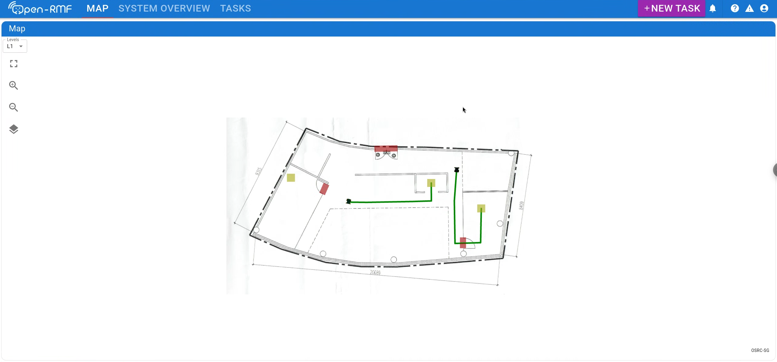
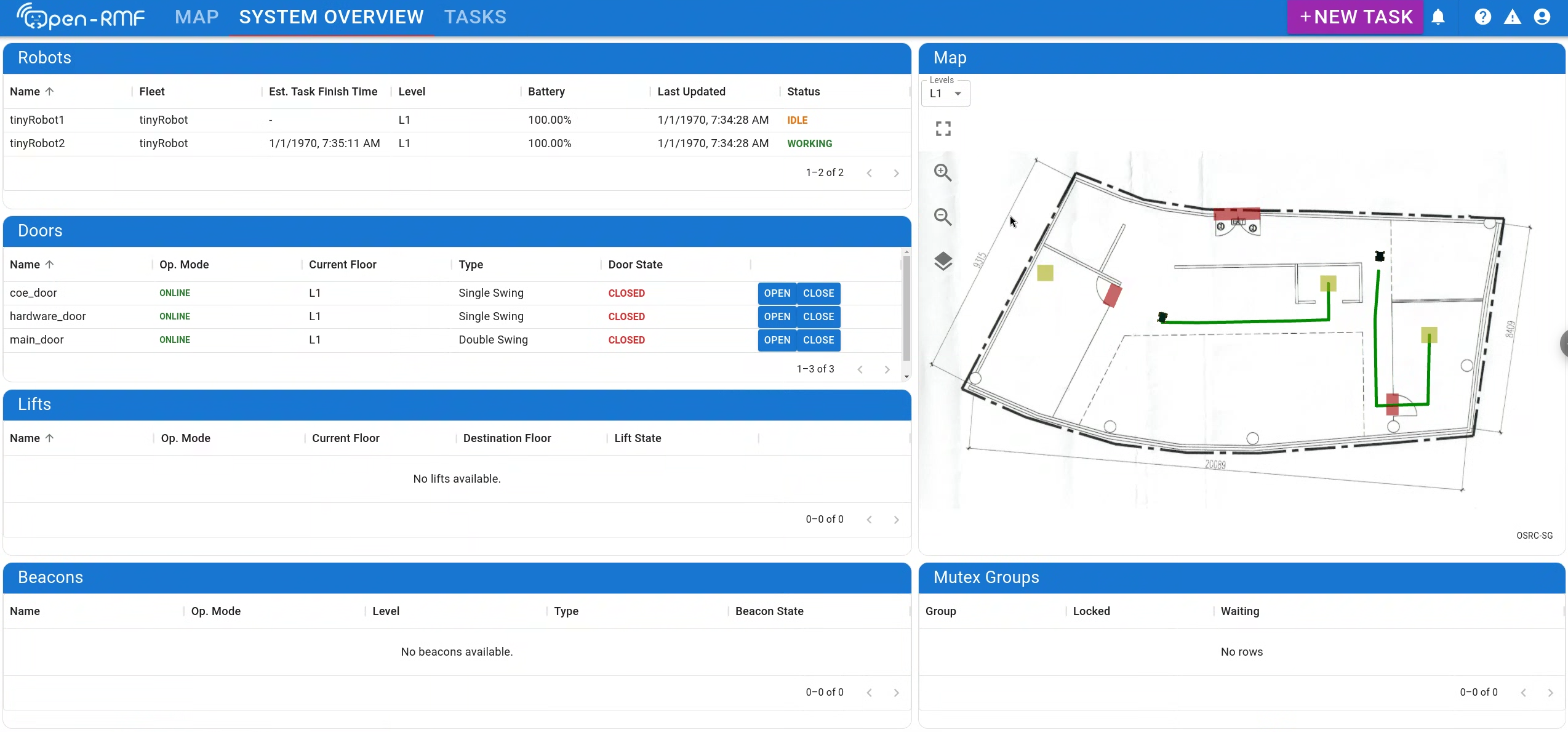
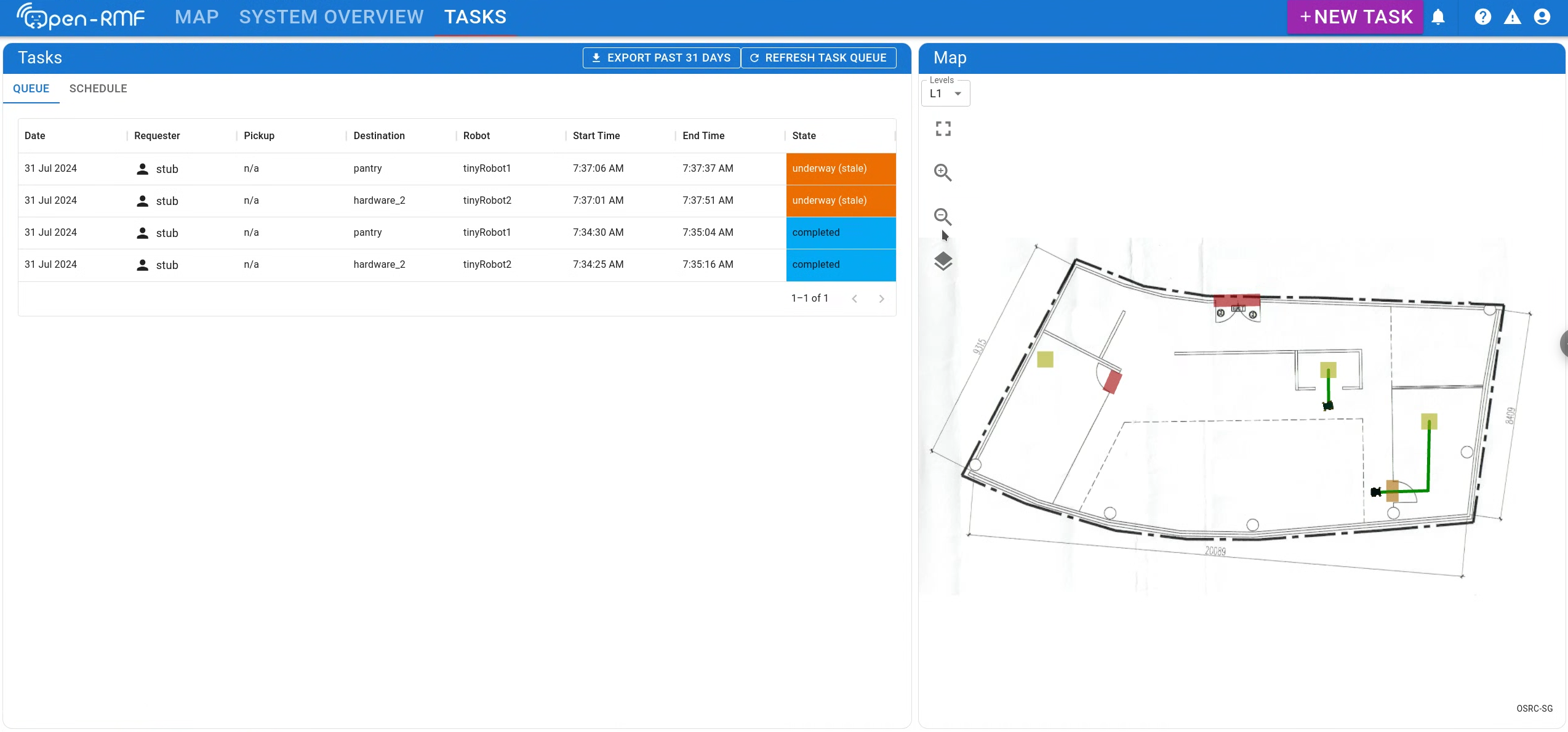
For users looking to set up a full deployment of Open-RMF with its core libraries, building infrastructure adapters, fleet adapters and Open-RMF web, please refer to the Open-RMF deployment template.
Related Repositories
UI
Certain portion of this doc is deprecated, please refer to rmf-web for the latest development.
Introduction
This chapter describes how we can write end user applications which integrate into RMF. We will briefly go through the requirements of an RMF UI application and provide a tutorial to write a React Webapp that interfaces with RMF.
Overview
The most common way to write a UI application is to make use of a UI framework. There are many available UI frameworks, the following are some of the popular frameworks for reference:
- Multi-Paradigm
- Qt
- React native
- Xamarin
- Flutter
- Web
- React
- Angular
- Vue
- Desktop
- wxWidgets
- Gtk
- WPF (Windows only)
Each framework has pros and cons and we do not feel there is a "best" framework for all use cases. That being said, some frameworks are more suitable to integrate with RMF due to their specific underlying technologies. To understand why, let's take a brief overview at how an RMF UI application would work.
How Does an RMF UI Application Work?
Imagine a simple UI application with a label that shows the current status of a door and a button that opens/closes the door. Recall that in the door adapter, we publish door states and subscribe to door requests. Here we are doing the reverse; subscribing to door states and publishing door requests. We will be listening to door states coming in from RMF and updating our display to match, and we will also be sending door requests when the user clicks the open or close button.
We need to use a libray to help us do that. In the hardware adapter examples we are using the rclcpp library, but rclcpp isn't the only way to use ROS 2. Here are some libraries that also work well
- Direct
- rcl (C)
- rclcpp (C++)
- rclpy (python)
- rclnodejs (nodejs)
- Indirect
- SOSS (websocket)
- rosbridge (websocket)
A "direct" library is able to send and receive ROS 2 messages directly from the application, in contrast, an indirect library uses a middleman service to forward ROS 2 messages. In general, the "direct" approach is more preferable but sometimes it is not possible on the target platform. In these cases, the indirect approach can be used.
ros2-dotnet project for example, provides C# bindings for ROS 2. You can also write your own bindings and middlewares!
Writing an RMF UI application isn't much different from writing any other UI application, the only difference being that we will be sending/receiving ROS 2 data in response to user input and updating the UI's state.
Tutorial: React WebApp
In this section, we will go through an example of creating a React-based webapp to monitor door states and send door open/close requests. The tutorial will focus on the aspects of communicating with RMF; basic knowledge of React and TypeScript is needed.
Note that this isn't the only way to create a RMF UI application, as mentioned before, you can use any UI toolkit, the only requirement is to be able to send/receive ROS 2 messages.
The code for this tutorial is available here.
Requirements
- nodejs >= 10
- rmf_core
- soss
- rmf-soss-ros2
- rmf_demos
We will not go through the process of setting up the dependencies, instructions to set them up can be easily found on the web or from their project homepages.
Setting Up
We will be using an example from rmf_demo as the RMF deployment that we will be interacting with. This is a good time to test if your installation of rmf_demo is working properly, start the demo with the following command:
ros2 launch demos office.launch.xml
Next let's test if SOSS is working. In order to run SOSS, you need to provide it with a configuration file; you can use this template as a start. You would need a certificate for SOSS; refer to various tutorials online to generate one. If you are using a self-signed cert, also make sure your browser is set to accept it for websocket connections. Add the path of your cert and key to the SOSS config and try starting SOSS with:
soss <path_to_config>
Once the environment is set up, we can then proceed to set up our actual app. First, create a React workspace with:
npx create-react-app react-app-tutorial --template typescript
Go inside the newly created react-app-tutorial directory and run the following command to install all the JavaScript dependencies we will be using:
npm install @osrf/romi-js-core-interfaces @osrf/romi-js-soss-transport jsonwebtoken @types/jsonwebtoken
These libraries are not strictly required but they contain helpful functions to use soss and to communicate with RMF. If you are building a JavaScript-based RMF app, it is recommended to make use of them, we will see later how they simplify the communication to RMF.
@osrf/romi-js-soss-transport, there is also @osrf/romi-js-rclnodejs-transport which is able to send ROS 2 messages directly, however it does not work on the browser. It is preferred if you are writing a Node.js based desktop application using something like Electron, or you are writing a server based application like a REST API provider.
Door Component
First of all, let's start things simple by creating a component to show a door's state along with open and close buttons. Create a new file called Door.tsx in react-app-tutorial/src directory and copy the below snippet into it.
import React from 'react';

export interface DoorProps {
  name: string;
  state: string;
  onOpenClick?(e: React.MouseEvent): void;
  onCloseClick?(e: React.MouseEvent): void;
}

export const Door = (props: DoorProps) => {
  const { name, state, onOpenClick, onCloseClick } = props;
  return (
    <div>
      Door: {name}
      <br />
      State: {state}
      <br />
      <button onClick={(e) => onOpenClick && onOpenClick(e)}>Open</button>
      <button onClick={(e) => onCloseClick && onCloseClick(e)}>Close</button>
      <br />
      <br />
    </div>
  );
};

export default Door;
Nothing much is happening here yet. We are simply rendering the door name, its state and open and a close button.
Let's test things out by running it. Replace App.tsx with this:
import React from 'react';
import Door from './Door';

function App() {
  return <Door name="example_door" state="Closed" />;
}

export default App;
and start it with npm start. You should see something like this:
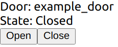
Great! We now have a base to start implementing the rest of the app.
Obtain List of Doors
Previously we made a simple door component and tested rendering it with hard-coded values. Obviously this won't work in a proper app, so here we will look at how we can obtain the list of actual doors from RMF.
Start of by adding a React state to track the list of doors:
const [doors, setDoors] = React.useState<RomiCore.Door[]>([]);
RMF has a get_building_map service that we can use to get the list of doors, lifts, levels among many other data, in order to make use of the service we need to do a ROS 2 service call, since there isn't ROS 2 support on the browser, we will be using an "indirect" approach with soss. A websocket connection is made to SOSS which will then act as a middleman and pass our messages to the ROS 2 network.
An easy way to use SOSS is with the @osrf/romi-js-soss-transport package, so let's do it now. Add a react effect hook to your App component
  React.useEffect(() => {
    (async () => {
      const token = jwt.sign({ user: 'example-user' }, 'rmf', { algorithm: 'HS256' });
      const transport = await SossTransport.connect('example', 'wss://localhost:50001', token);
    })();
  }, []);
We will need to import SossTransport, so add this to the top of the file:
import { SossTransport } from '@osrf/romi-js-soss-transport';
This performs a websocket connection to the SOSS server. example is the ROS 2 node name that we will be using, and we are connecting to a SOSS server at wss://localhost:50001. The server uses a JWT token signed with a secret specified in the SOSS config. The example config is using rmf. If you changed the secret, be sure to change it here as well.
Now that we have a connection to SOSS, we can call the get_building_map service. Add this to the React effect:
const buildingMap = (await transport.call(RomiCore.getBuildingMap, {})).building_map;
setDoors(buildingMap.levels.flatMap((level) => level.doors));
It uses RomiCore, so add this to your imports:
import * as RomiCore from '@osrf/romi-js-core-interfaces';
This downloads and parses the building map from RMF. romi-js simplifies a ROS 2 service call with the async call method. If you are familiar with rclnodejs, this is roughly equivalent to:
const client = node.createClient(
  'building_map_msgs/srv/GetBuildingMap',
  'get_building_map'
);
client.sendRequest({}, response => {
  const buildingMap = response.building_map;
  setDoors(buildingMap.levels.flatMap((level) => level.doors));
});
Notice that we need to provide it with type of the message (building_map_msgs/srv/GetBuildingMap) and the name of the service (get_building_map), but how do we find out what the service name and type are? We could read the RMF manual or query the ROS 2 system while RMF is running. Another way is with the help of RomiCore; it provides a list of known RMF services and messages so you don't have to go through the trouble of finding them yourself.
In the below statement, we are using RomiCore to call the get_building_map service without needing to know the service name and types:
transport.call(RomiCore.getBuildingMap, {})
Now that we have a list of RomiCore.Door, let's make things simpler by updating Door.tsx to take that in as a prop. While we're at it, let's also have it take in a RomiCore.DoorState as a prop since we will be using it later.
Door.tsx:
import * as RomiCore from '@osrf/romi-js-core-interfaces';
import React from 'react';

export interface DoorProps {
  door: RomiCore.Door;
  doorState?: RomiCore.DoorState;
  onOpenClick?(e: React.MouseEvent): void;
  onCloseClick?(e: React.MouseEvent): void;
}

export const Door = (props: DoorProps) => {
  const { door, doorState, onOpenClick, onCloseClick } = props;
  return (
    <div>
      Door: {door.name}
      <br />
      State: {doorState ? doorState.current_mode.value : 'Unknown'}
      <br />
      <button onClick={(e) => onOpenClick && onOpenClick(e)}>Open</button>
      <button onClick={(e) => onCloseClick && onCloseClick(e)}>Close</button>
      <br />
      <br />
    </div>
  );
};

export default Door;
Now we can test it by passing the doors as props. Your App.tsx component should now look like this:
import * as RomiCore from '@osrf/romi-js-core-interfaces';
import { SossTransport } from '@osrf/romi-js-soss-transport';
import * as jwt from 'jsonwebtoken';
import React from 'react';
import Door from './Door';

function App() {
  const [doors, setDoors] = React.useState<RomiCore.Door[]>([]);

  React.useEffect(() => {
    (async () => {
      const token = jwt.sign({ user: 'example-user' }, 'rmf', { algorithm: 'HS256' });
      const transport = await SossTransport.connect('example', 'wss://localhost:50001', token);
      const buildingMap = (await transport.call(RomiCore.getBuildingMap, {})).building_map;
      setDoors(buildingMap.levels.flatMap((level) => level.doors));
    })();
  }, []);

  return (
    <React.Fragment>
      {doors.map((door) => (
        <Door door={door} />
      ))}
    </React.Fragment>
  );
}

export default App;
Don't worry about the door state for now. If everything goes well, you should see 3 doors that are in the building listed:
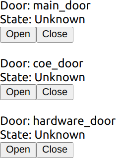
Listening for Door States
Previously we managed to render the list of doors in the RMF system, but the building map doesn't tell us the doors' states, so let's fix that. First, let's add a React state to track the door states:
const [doorStates, setDoorStates] = React.useState<Record<string, RomiCore.DoorState>>({});
The door states can be obtained by subscribing to the door_states topic. Add the following to your effect:
transport.subscribe(RomiCore.doorStates, (doorState) =>
  setDoorStates((prev) => ({ ...prev, [doorState.door_name]: doorState })),
);
This performs a ROS 2 subscription to the RomiCore.doorStates topic. Similar to the service call we did earlier, romi-js abstracts away the ROS 2 topic name and provides type information. The callback will be fired each time a new door state message comes in. In the callback, we simply update the doorStates state.
Now just pass the door state to the door component:
<Door door={door} doorState={doorStates[door.name]} />
The end result of your App.tsx should look like this:
import * as RomiCore from '@osrf/romi-js-core-interfaces';
import { SossTransport } from '@osrf/romi-js-soss-transport';
import * as jwt from 'jsonwebtoken';
import React from 'react';
import Door from './Door';

function App() {
  const [doors, setDoors] = React.useState<RomiCore.Door[]>([]);
  const [doorStates, setDoorStates] = React.useState<Record<string, RomiCore.DoorState>>({});

  React.useEffect(() => {
    (async () => {
      const token = jwt.sign({ user: 'example-user' }, 'rmf', { algorithm: 'HS256' });
      const transport = await SossTransport.connect('example', 'wss://localhost:50001', token);
      const buildingMap = (await transport.call(RomiCore.getBuildingMap, {})).building_map;
      setDoors(buildingMap.levels.flatMap((level) => level.doors));

      transport.subscribe(RomiCore.doorStates, (doorState) =>
        setDoorStates((prev) => ({ ...prev, [doorState.door_name]: doorState })),
      );
    })();
  }, []);

  return (
    <React.Fragment>
      {doors.map((door) => (
        <Door door={door} doorState={doorStates[door.name]} />
      ))}
    </React.Fragment>
  );
}

export default App;
And just like that we now have the door states!
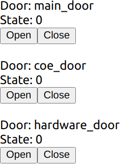
The door states are numbers like 0, 1 and 2. This is because RMF uses a constant to represent door states. We could run a simple function to convert these constants into strings:
function doorModeString(doorMode: RomiCore.DoorMode): string {
  switch (doorMode.value) {
    case 2:
      return 'Open';
    case 0:
      return 'Closed';
    case 1:
      return 'Moving';
    default:
      return 'Unknown';
  }
}
But how do we know 2 means "Open" etc? We can find out by reading the RMF manual or inspecting the ROS 2 message definitions, but we can do better with RomiCore. It provides the list of constants in a more readable form:
function doorModeString(doorMode: RomiCore.DoorMode): string {
  switch (doorMode.value) {
    case RomiCore.DoorMode.MODE_OPEN:
      return 'Open';
    case RomiCore.DoorMode.MODE_CLOSED:
      return 'Closed';
    case RomiCore.DoorMode.MODE_MOVING:
      return 'Moving';
    default:
      return 'Unknown';
  }
}
With this it's obvious what each constant represents so we don't have to refer to anything else to find its meaning.
Go ahead and add this to your Door.tsx. It should look like this now:
import * as RomiCore from '@osrf/romi-js-core-interfaces';
import React from 'react';

export interface DoorProps {
  door: RomiCore.Door;
  doorState?: RomiCore.DoorState;
  onOpenClick?(e: React.MouseEvent): void;
  onCloseClick?(e: React.MouseEvent): void;
}

export const Door = (props: DoorProps) => {
  const { door, doorState, onOpenClick, onCloseClick } = props;
  const modeString = doorState ? doorModeString(doorState.current_mode) : 'Unknown';
  return (
    <div>
      Door: {door.name}
      <br />
      State: {modeString}
      <br />
      <button onClick={(e) => onOpenClick && onOpenClick(e)}>Open</button>
      <button onClick={(e) => onCloseClick && onCloseClick(e)}>Close</button>
      <br />
      <br />
    </div>
  );
};

function doorModeString(doorMode: RomiCore.DoorMode): string {
  switch (doorMode.value) {
    case RomiCore.DoorMode.MODE_OPEN:
      return 'Open';
    case RomiCore.DoorMode.MODE_CLOSED:
      return 'Closed';
    case RomiCore.DoorMode.MODE_MOVING:
      return 'Moving';
    default:
      return 'Unknown';
  }
}

export default Door;
Great! Now we have readable door states instead of cryptic numbers.
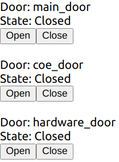
Sending Door Requests
As you may have expected by now, all we have to do here is to send door requests to RMF.
First, create a publisher. Add this to the start of the render function:
const doorRequestPub = React.useRef<RomiCore.Publisher<RomiCore.DoorRequest> | null>(null);
Then add this helper function:
const requestDoor = (door: RomiCore.Door, mode: number) => {
  if (doorRequestPub.current) {
    const request: RomiCore.DoorRequest = {
      door_name: door.name,
      request_time: RomiCore.toRosTime(new Date()),
      requested_mode: { value: mode },
      requester_id: 'example-request',
    };
    doorRequestPub.current.publish(request);
  }
};
It takes in a RomiCore.Door and a number representing the desired mode, and crafts a RomiCore.DoorRequest message and sends it using the publisher. Normally you would have to consult the RMF manual or the ROS 2 definitions to know exactly what you need to send. Again, RomiCore provides the typing information to make it easier to fill in the required fields.
Finally, add this to the props passed to the door component:
onOpenClick={() => requestDoor(door, RomiCore.DoorMode.MODE_OPEN)}
onCloseClick={() => requestDoor(door, RomiCore.DoorMode.MODE_CLOSED)}
Your final App.tsx should look like this:
import * as RomiCore from '@osrf/romi-js-core-interfaces';
import { SossTransport } from '@osrf/romi-js-soss-transport';
import * as jwt from 'jsonwebtoken';
import React from 'react';
import Door from './Door';

function App() {
  const [doors, setDoors] = React.useState<RomiCore.Door[]>([]);
  const [doorStates, setDoorStates] = React.useState<Record<string, RomiCore.DoorState>>({});
  const doorRequestPub = React.useRef<RomiCore.Publisher<RomiCore.DoorRequest> | null>(null);

  React.useEffect(() => {
    (async () => {
      const token = jwt.sign({ user: 'example-user' }, 'rmf', { algorithm: 'HS256' });
      const transport = await SossTransport.connect('example', 'wss://localhost:50001', token);
      const buildingMap = (await transport.call(RomiCore.getBuildingMap, {})).building_map;
      setDoors(buildingMap.levels.flatMap((level) => level.doors));

      transport.subscribe(RomiCore.doorStates, (doorState) =>
        setDoorStates((prev) => ({ ...prev, [doorState.door_name]: doorState })),
      );

      doorRequestPub.current = transport.createPublisher(RomiCore.adapterDoorRequests);
    })();
  }, []);

  const requestDoor = (door: RomiCore.Door, mode: number) => {
    if (doorRequestPub.current) {
      const request: RomiCore.DoorRequest = {
        door_name: door.name,
        request_time: RomiCore.toRosTime(new Date()),
        requested_mode: { value: mode },
        requester_id: 'example-request',
      };
      doorRequestPub.current.publish(request);
    }
  };

  return (
    <React.Fragment>
      {doors.map((door) => (
        <Door
          door={door}
          doorState={doorStates[door.name]}
          onOpenClick={() => requestDoor(door, RomiCore.DoorMode.MODE_OPEN)}
          onCloseClick={() => requestDoor(door, RomiCore.DoorMode.MODE_CLOSED)}
        />
      ))}
    </React.Fragment>
  );
}

export default App;
Try clicking on the open and close buttons now. You should see the door state being updated. You can also see the door opening/closing in Gazebo. Congratulations, you have just written a simple RMF UI application! Obviously the design leaves much to be desired as we didn't do any CSS styling but that is outside the scope of this tutorial.
Extending this to provide more features like lift control, fleet states, etc. follows the same principle. All the available topics and services exposed by RMF are available in RomiCore and you can find more detailed information by reading the rest of the manual. This also extends to writing UI applications for other platforms and frameworks; at the core you are really just publishing and subscribing to ROS 2 messages so you can apply the same principles to other languages and frameworks.
Conclusion
We have just created a minimal RMF UI application that reports the door state and allows a user to control the door. For simplicity, there aren't many features included but this tutorial should provide the basic knowledge of how to create an RMF UI application not only in React but also in any framework that you like.
If you would like more examples of a React RMF application, you can take a look at the official RoMi dashboard.
Extra: Extending romi-js
Throughout the tutorial, we used romi-js to simplify the communication to RMF. As you might have noticed romi-js is actually a collection of packages. This design makes it possible to easily extend it with new topics, services and even transports.
Adding Topics and Services
Topics and services are defined by the interfaces:
export interface RomiTopic<Message> {
  readonly validate: (msg: any) => Message;
  readonly type: string;
  readonly topic: string;
  readonly options?: Options;
}

export interface RomiService<Request, Response> {
  readonly validateRequest: (msg: any) => Request;
  readonly validateResponse: (msg: any) => Response;
  readonly type: string;
  readonly service: string;
  readonly options?: Options;
}
If you are familiar with ROS 2, the type field specifies the message type that the topic or service expects while topic/service are the topic and service names, respectively. Sometimes a topic or service is expected to use a different QoS option; for example a topic that does not publish when the state changes and expects late subscriptions to make use of transient local QoS to receive the latest state. The options specify the "default" QoS options that should be used. In this way, users do not have to refer to the usage instructions to correctly publish and subscribe to the topic.
The validate* methods are used by the transport to convert an arbitrary object to the expected type of the topic or service. It should check if the object has the correct fields and that the fields are of the correct types. To ensure compatibility with different transports, these methods should be able to convert number arrays to typed arrays and vice versa.
We can create custom topics or services by implementing these interfaces. They can then be passed to the transport's various methods.
export const myTopic: RomiTopic<MyMessage> = {
  validate: validateMyMessage(msg), // some function that valides MyMessage
  type: 'my_messages/msg/MyMessage',
  topic: 'my_topic',
};
Adding Transport
A Transport in romi-js is a class with the interface:
export interface Subscription {
  unsubscribe(): void;
}

export interface Publisher<Message> {
  publish(msg: Message): void;
}

export interface Service<Request, Response> {
  start(handler: (req: Request) => Promise<Response> | Response): void;
  stop(): void;
}

export interface Transport extends TransportEvents {
  readonly name: string;

  createPublisher<Message extends unknown>(
    topic: RomiTopic<Message>,
    options?: Options,
  ): Publisher<Message>;

  subscribe<Message extends unknown>(
    topic: RomiTopic<Message>,
    cb: SubscriptionCb<Message>,
    options?: Options,
  ): Subscription;

  call<Request extends unknown, Response extends unknown>(
    service: RomiService<Request, Response>,
    req: Request,
  ): Promise<Response>;

  createService<Request extends unknown, Response extends unknown>(
    service: RomiService<Request, Response>,
  ): Service<Request, Response>;

  destroy(): void;
}
There isn't a general guide on how the interface should be implemented since the details would be different for each transport. One thing to note is that it might be tempting to return a type derived from any (e.g. Publisher<any>) to pass the typescript checks but doing so is not recommended. You should call the validate* methods in the topic or service to convert something into a type of Message.
To ensure compatibility with different topics and services, transports must de-serialize the data to a plain old data object. It can use either number arrays or typed arrays. The validate* methods should support converting them to the expected types.
Security
This chapter describes how to use DDS Security tools to provide authentication, encryption, and access control to an RMF system.
The security of the RMF system can be divided into two main parts: its ROS 2 elements and the dashboard. The security of the ROS 2 elements is provided by the DDS security tools which help ensure authentication, encryption and access control. The dashboard provides the user with an instruments panel while ensuring encryption, integrity and authentication of the connection to the server through TLS. User authentication and access control is made by user/password checking against a database and then providing that user with access to the secured ROS 2 network at a level that corresponds to the role of that user.
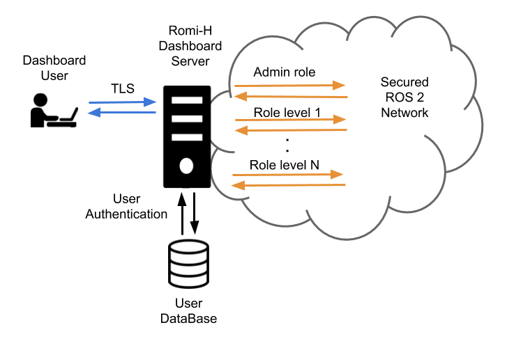
The RMF Demos Office World repository contains an example of a full RMF application using secured ROS 2 communications along with step by step explanations.
ROS 2 Security
ROS 2 contains tools that help create and load the needed security artifacts to enable DDS-security. RMF makes uses of these tools in order to enable security on its ROS 2 elements. A brief introduction to these tools and its usage is provided here. For a deeper understanding of the whole system, please refer to the ROS 2 DDS-Security integration documentation.
DDS-Security overview
The DDS-Security specification expands upon the DDS specification, adding security enhancements by defining a Service Plugin Interface (SPI) architecture, a set of builtin implementations of the SPIs, and the security model enforced by the SPIs. Specifically, there are five SPIs defined:
- Authentication: Verify the identity of a given domain participant.
- Access control: Enforce restrictions on the DDS-related operations that can be performed by an authenticated domain participant.
- Cryptographic: Handle all required encryption, signing, and hashing operations.
- Logging: Provide the ability to audit DDS-Security-related events.
- Data tagging: Provide the ability to add tags to data samples.
ROS 2's security features currently utilize only the first three. This is due to the fact that neither Logging nor Data Tagging are required in order to be compliant with the DDS-Security spec (see section 2.3), and thus not all DDS implementations support them.
SROS 2 tools
Since the DDS-Security plugins require a set of security files per domain participant, these need to be created beforehand in order to provide authentication, access control and encryption to the ROS 2 elements of RMF. Domain participants usually map to a context within the process in ROS 2, therefore each process will require a set of these files.
Since SROS 2 has no support for launch files yet, each binary needs to be launched separately
on its own terminal. Alternatively we recommend the creation of scripts to automate this process.
An example of this is the tmux script used in the [Office SROS 2 demo][https://github.com/open-rmf/rmf_demos/blob/main/docs/secure_office_world.md].
The ros2 security command is the way to access the SROS 2 set of tools to create and manage
your DDS-security artifacts. You can get a glimpse at its features by accessing the documentation
through the -h flag:
$ ros2 security -h
usage: ros2 security [-h] Call `ros2 security <command> -h` for more detailed usage. ...

Various security related sub-commands

optional arguments:
  -h, --help            show this help message and exit

Commands:
  create_key          Create key
  create_keystore     Create keystore
  create_permission   Create permission
  generate_artifacts  Generate keys and permission files from a list of identities and policy files
  generate_policy     Generate XML policy file from ROS graph data
  list_keys           List keys

  Call \`ros2 security <command> -h\` for more detailed usage.
SROS 2 environment variables
There are a few environment variables you should be aware of when using SROS 2:
- ROS_SECURITY_ENABLE is the SROS 2 enabler variable, it takes a boolean value (true or false) and indicates if the security is enabled or not.
- ROS_SECURITY_STRATEGY can be set to
EnforceorPermissive, with the first one it will fail to run a participant if the security files are not found, whereas with the second one will just run the participant in non secure mode if those files are not found. - ROS_SECURITY_KEYSTORE should point to the root of the keystore directory tree. This will help
RCLfind the location of the security artifacts to initialize the ROS 2 security environment.
SROS 2 security keystore
The keystore is the root directory where the DDS security artifacts are stored. RCL will use the
contents of this directory to provide the DDS security to the ROS 2 network. The
ROS_SECURITY_KEYSTORE environment variable should by convention point to this directory. In order
to initalize and populate keystore_storage directory files the following command can be used:
$ ros2 security create_keystore keystore_storage
creating keystore: keystore_storage
creating new CA key/cert pair
creating governance file: keystore_storage/enclaves/governance.xml
creating signed governance file: keystore_storage/enclaves/governance.p7s
After creating the keystore, its initial structure would look like this:
keystore_storage
├── enclaves
|   ├── governance.p7s
|   └── governance.xml
├── private
|   ├── ca.key.pem
|   ├── identity_ca.key.pem
|   └── permissions_ca.key.pem
└── public
    ├── ca.key.pem
    ├── identity_ca.key.pem
    └── permissions_ca.key.pem
The public directory contains anything permissible as public, such as public certificates for
the identity or permissions Certificate Authorities (CA). As such, this can be given read access to all
executables. Note that in the default case, both identity_ca and permissions_ca point to the
same CA certificate.
The private directory contains anything permissible as private, such as private key material for
aforementioned certificate authorities. This directory should be removed before deploying the
keystore onto the target device/robot.
The enclaves directory contains the security artifacts associated with individual security enclaves.
SROS 2 introduces the concept of a security “enclave”,
where an “enclave” is a process or group of processes that will share the same identity and access
control rules. The enclaves folder may recursively nest sub-paths for organizing separate enclaves.
SROS 2 enclave keys
Once the keystore has been initialized you may wish to create the security keys for your
enclaves. This will populate the enclaves directory with the necessary keys and governance
files. As an example, in order to create the security files for our/hospital/rviz enclave the
following command would be issued:
$ ros2 security create_key keystore_storage /hospital/rviz
creating key for identity: '/hospital/rviz'
creating cert and key
creating permission
After this, they keystore_storage directory should contain the rviz enclave:
keystore_storage
├── enclaves
|   ├── governance.p7s
|   ├── governance.xml
│   └── hospital
|       ├── rviz
│       |   ├── cert.pem
│       |   ├── key.pem
│       |   ├── governance.p7s
|       |   ├── identity_ca_cert.pem
|       |   ├── permissions_ca.cert.pem
|       |   ├── permissions.p7s
|       |   └── permissions.xml
...     ...
Now there is an enclave containing the following files:
- identity_ca.cert.pem: The x.509 certificate of the CA trusted by the Authentication plugin (the "Identity" CA).
- cert.pem: The x.509 certificate of this enclave instance (signed by the Identity CA).
- key.pem: The private key of this enclave instance.
- permissions_ca.cert.pem: The x.509 certificate of the CA trusted by the Access control plugin (the "Permissions" CA).
- governance.p7s: The XML document that specifies to the Access control plugin how the domain should be secured (signed by the Permissions CA).
- permissions.p7s: The XML document that specifies the permissions of this particular enclave instance to the Access control plugin (also signed by the Permissions CA).
SROS 2 access control
In order to provide access control the security permissions need to be added to the permissions files
of the enclave and signed by the CA. In order to do this a policy file following the
SROS 2 policy schema is needed.
This file specifies the permissions awarded to the enclave within the ROS 2 network.
To create and sign the permissions the create_permission option can be used:
$ ros2 security create_permission keystore_storage /hospital/rviz policy.xml
creating permission file for identity: '/hospital/rviz'
creating permission
After running this command, the permissions.p7s and permissions.xml files for the
enclave /hospital/rviz will contain the signed permissions specified in policy.xml.
We will have to specify this enclave through rosargs when starting our process:
$ ros2 run <package> <executable> --rosargs ---enclave /hospital/rviz
SROS 2 automated generation
The process of generating keys and permissions can be sometimes tedious, so SROS 2 provides tools to automate this process. An automated way to generate the policy is provided, it can be triggered by running the following command:
$ ros2 security generate_policy policy.xml
This command will take the ROS graph at the point of running and generate the policy.xml file that corresponds to it. Note that this, as it only uses the current ROS graph as a source of information, might still miss policies for future publishers, subscribers, services or others.
The process and key and permissions generation can also be troublesome, SROS 2 provides a command that you can use to generate all of them at once:
$ ros2 security generate_artifacts -k keystore_storage -p policy.xml
keystore_storage is not a valid keystore, creating new keystore
creating keystore: keystore_storage
creating new CA key/cert pair
creating governance file: keystore_storage/enclaves/governance.xml
creating signed governance file: keystore_storage/enclaves/governance.p7s
all done! enjoy your keystore in keystore_storage
cheers!
creating key for identity: '/hosptial/rviz'
creating cert and key
creating permission
creating permission file for identity: '/hosptical/rviz'
creating permission
...
Finally SROS 2 also provides a way to easily list the keys of a certain keystorage:
$ ros2 security list_keys keystore_storage
/hospital/building_map_server
/hopsital/building_systems_visualizer
/hospital/door_supervisor
/hospital/fleet_state_visualizer
/hosptial/loop_request_publisher
/hosptial/rviz2
...
RMF Web Dashboard Security
[RMF Web] (https://github.com/open-rmf/rmf-web) is a web application that provides overall visualization and control over the RMF system. It is served over TLS to ensure encryption, integrity and authentication of the communication with the final user. The server uses openid-connect (OIDC) for authentication, an open standard based on oauth 2.0 and JOSE. Currently the dashboard makes use of Keycloack, an open source implementation of OIDC. It provides an user management system, which is used to create/delete users. Each user gets assigned a role which is reflected on an id token generated on the user. This id token is signed securely and sent to the api server which it can then look at the role of the user and act accordingly. The api server runs a secured ROS 2 node per each role and provides access to them based on the id token of each user.
Roadmap
This page describes topics that we are currently working on and expect to advance in the next 12 months. We can’t commit to specific development timelines, but community feedback on which topics are of highest interest is one factor that can help influence the prioritization of our work queue. As in any R&D project, we will react to how things evolve in many dimensions.
Open-RMF is an open-source project. We will keep developing in the open so that community members can see real-time what is happening. Let's work on it together! We encourage (and really love to see!) contributions from the community in addition to our own efforts, so if you see something that interests you, please collaborate with us through GitHub!
Scalability
When it comes to multi-robot coordination, scalability is a complex topic with many separate facets, and every one of those facets is crucial to the overall story. Concerns about scalability can be viewed in terms of variables and their resulting costs.
Variables
- A. Number of mobile robots sharing space
- B. Capabilities of each mobile robot
- C. Size of the space being shared
- D. Severity of narrow passages and bottlenecks
- E. System network topology (LAN, wired, Wi-Fi, remote/cloud)
Costs
- 1. Computing resources (CPU load, RAM)
- 2. Time to find solutions
- 3. Quality of solutions (how close to being globally optimal, Pareto efficient, or another criteria)
- 4. Quality of operation (responsiveness, smooth execution)
This table breaks down ongoing efforts to improve scalability, specifying which variables will scale better and which resulting costs will be improved. See below the table for detailed descriptions of each improvement.
| Improvement | A | B | C | D | E | 1 | 2 | 3 | 4 |
|---|---|---|---|---|---|---|---|---|---|
| Reservation System | ✅ | ✅ | ✅ | ✅ | ✅ | ||||
| Queuing System | ✅ | ✅ | ✅ | ✅ | ✅ | ✅ | |||
| Hierarchical Planning | ✅ | ✅ | ✅ | ✅ | ✅ | ||||
| Custom Negotiation | ✅ | ✅ | ✅ | ✅ | |||||
| Zenoh | ✅ | ✅ | ✅ | ✅ | ✅ |
Reservation System
Initially described here the reservation system would assign relevant resources to robots in a globally optimal way. Originally conceived for parking spaces, it will also be applicable for elevator and workcell usage.
Queuing System
Initially described here, when multiple robots need to use one resource in a sequence (e.g. passing through a door), the queuing system will manage a rigidly defined queuing procedure instead of relying on the traffic negotiation system to resolve the use of the narrow corridor.
Hierarchical Planning
Hierarchical traffic planning would decompose the overall planning space into regions separated by chokepoints. Each chokepoint would be managed by a queue. The traffic negotiation system would only account for traffic conflicts that happen while robots transition from one queue to another queue. Reducing the scope of conflicts will make negotiations faster, less frequent, and less CPU intensive.
Custom Negotiation
Not all mobile robots or uses cases will fit neatly into the three out-of-the-box categories of "Full Control", "Traffic Light", and "Read-Only". Letting system integrators fully customize the way the fleet adapter plans and negotiates for their robot will allow Open-RMF to support more types of robots with better outcomes.
Zenoh
There are various inefficiencies in the ROS 2 implementation of Open-RMF related to DDS discovery mechanisms and the absence of message key support within ROS 2. Using Zenoh, either directly or as an RMW implementation with ROS 2, would allow for significantly more efficient communication, especially over Wi-Fi networks and for large numbers of agents and subsystems.
Tools
Managing and understanding large-scale complex systems requires tools that are able to provide comprehensive insight into how the system is operating and why. We are pushing forward efforts to develop the Site Editor into a baseline for a visualization, event simulation, and digital twin tool that can help developers and end-users alike see what is going in an Open-RMF system (whether simulated or deployed) and why. The planned capabilities are:
- Large-scale event-driven simulation (simulating hundreds of mobile robots and other Open-RMF systems in real time or faster-than-real time)
- Digital twin 3D view of a live deployment, with visualizations of decisions that are being made
- Debugging tools to look into plans and negotiations, with visualizations that explain why each solution was produced
Capabilities
To expand the scope of where and how Open-RMF can be used, we are also planning new capabilities:
- Free space traffic negotiation
- Describing tasks by drawing behavior diagrams
- Support multi-agent tasks with parallel threads of activity
- Allow constraints to be defined between tasks
Developer Experience
For wider adoption and quicker deployment, we want to improve the developer experience for system integrators.
- Simpler APIs that allow greater customization of robot behaviors
- Easier integration options, such as a "native" integration with the ROS 2 Nav Stack
- We will provide a ROS 2 nav stack plugin that gives Open-RMF compatibility to any robot using it
- More documentation, including updating this book
- Interactive tutorials in the site editor
Introduction
How-to Guides provide direct and modular answers to “How-to” questions regarding specific topics you may have about Open-RMF.
They contain step-by-step instructions you can follow to quickly get started with key aspects of Open-RMF that are not covered in previous sections.
If there are any interesting topics you would like to contribute, feel free to open a Pull Request here.
Navigation Graph Strategies
This section elaborates on a few feature-driven strategies that would help optimize traffic flow. Many of them can be set up when creating your navigation graph, which is necessary for RMF integration with mobile robot fleets. The instructions and screenshots are specific to the RMF Traffic Editor tool. If this is your first time setting up a navigation graph, the Traffic Editor section in this Book goes into detail how to use the RMF Traffic Editor to create one. Do note that this is a legacy tool, and that there is an experimental RMF Site Editor under rapid development.
Important Considerations
Before setting up your navigation graph, consider the following for both physical and simulation integrations:
- Determine where your robots will be allowed to travel - visualize waypoints and lanes for these areas
- Plan for charger location(s) - at least one charger is required for each fleet
- Ensure sufficient space for your mobile robot to move around, leaving some room between waypoints and lanes. The amount of space required increases with the number of robots that will be integrated.
- Each area should be spacious enough to accommodate the maximum number of robots in your site. This includes adding the appropriate number of waypoints to handle these robots.
- Allocate space for holding points where possible to facilitate deconfliction
Unidirectional Lanes
Lanes in RMF can be unidirectional or bidirectional. When a lane is unidirectional, robots can only travel across the lane from a specific start waypoint to an end waypoint, essentially restricting travel to a single direction. This can come in handy for tight spaces, lift entry/exits, and other scenarios where one-way traffic is needed. For example, when multiple robots are moving within an area where space may be constrained, unidirectional lanes can be used to create a traffic flow, reducing the risk of head-on conflicts between robots.
Example 1: Multiple robots visiting the same waypoint
This example illustrates multiple robots attempting to visit the same waypoint, lot_A_pickup, at the same time. The unidirectional lanes create a loop system that allows robots to access the waypoint one by one in a single direction.
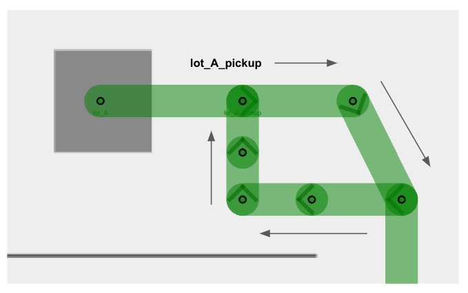
Example 2: Lift entry and exit
Similarly, users are encouraged to make lift entry and exit lanes unidirectional, so as to facilitate robot movement in cases where a robot_A is exiting the lift, and a robot_B waiting to enter the lift. By creating separate lanes for each event and restricting their direction flow, the robots will less likely come into a deadlock and hold up an important building infrastructure that is the lift.
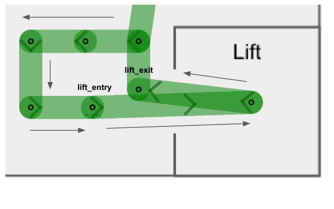
You will notice that in both examples there are several intermediate waypoints allotted. This is because these examples are designed to accommodate a site with five robots, and assigning more waypoints than the maximum number of robots help to ensure free space for each robot integrated.
Mutex Groups
The concept of mutex groups was introduced to provide users with extra control over traffic flow between robots. Waypoints and lanes can be assigned to a mutex group. At any point of time, only one robot is allowed to occupy any waypoint or lane belonging to the same mutex group. By implementing them stragetically in navigation graphs, users can further enhance RMF's deconfliction capabilities to prevent deadlocks and clutter in a given space.
-
Mutex groups can be assigned when designing your navigation graph. In the traffic editor, select an existing waypoint or lane, and add the
mutexproperty to it.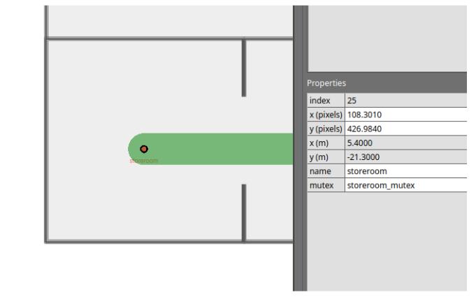
-
Mutex groups are differentiated by name. To assign a group of waypoints and lanes to the same mutex group, you simply have to provide a unique name when adding the
mutexproperty. -
You will not be able to assign multiple mutex groups to a single waypoint or lane.
-
Mutex groups are obtained on a first-come-first-served basis.
Example: Storeroom entry with queue
Imagine you have a storeroom with limited space, which only allows for one robot to enter at a time. With multiple robots tasked to enter the same room, you'd like them to queue up outside when the storeroom is occupied. You may design your navigation graph like this:
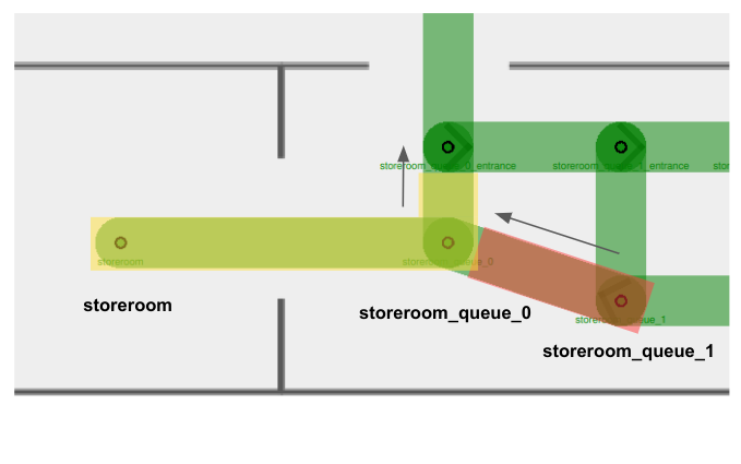
This example combines the use of unidirectional lanes (to set up a queueing system) and mutex groups (to ensure vacant waypoints for storeroom exits).
- There are two mutex groups in this example:
storeroom_mutexhighlighted in yellow, andstoreroom_queue_1_mutexhighlighted in red. - Arrows indicate unidirectional lanes.
- Notice that both waypoints
storeroomandstoreroom_queue_0, as well as the lane connecting them, belong to thestoreroom_mutex(in yellow). This ensures that when there is arobot_Ainside the storeroom, no other robots will be allowed on the waypointstoreroom_queue_0despite it being unoccupied. This way,robot_Acan smoothly exit the storeroom without facing a deadlock with an incoming robot. - When you assign a mutex group to a waypoint, you are also encouraged to assign the same mutex group to the lane(s) it uses to leave the waypoint. This is especially important for tight spaces where you'd need to ensure that a waypoint is completely vacant before the next robot starts moving in.
- Taking
storeroom_queue_1_mutex(in red) as an example, if there is arobot_Bsitting on the waypointstoreroom_queue_1and is moving towardsstoreroom_queue_0, the mutex in red would still be held whilerobot_Bis travelling on the departure lane. - Other robots will not be able to begin travelling towards
storeroom_queue_1whilerobot_Bis moving away. - This mutex will only be released when
robot_Bhas arrived atstoreroom_queue_0, making space for the next robot to move tostoreroom_queue_1.
- Taking
Lane Closure
RMF supports lane closure at runtime. When a LaneRequest is published, RMF will update the navigation graph with any lane openings or closures. No robots will be commanded to travel on a closed lane until it is marked as open again.
While this feature is primarily useful for site maintenance and other situations where an area should be temporarily off-limits to robots, it also allows for custom conditional lane traversal.
Example 1: Maximum room occupancy
Lane closures can be useful to optimize queue systems. Consider the above example where robots are queueing to enter a storeroom.
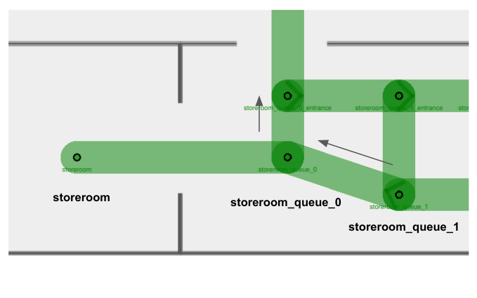
Suppose a robot_A is currently inside the storeroom, and robot_B, robot_C, robot_D and robot_E are all tasked to enter the same room. If we do not define a queueing system for our robots, it is possible for them to come in from any origin and clutter the storeroom entrance like this:
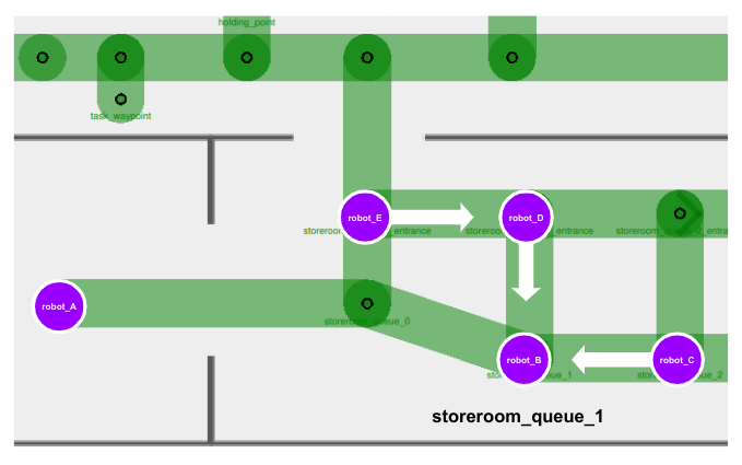
This is undesirable as there is no queue or sequence formed for waiting robots to enter the storeroom systematically. Furthermore, there is a possibility of waiting robots to block the storeroom exit, e.g. robot_E, creating a deadlock in this area.
At the same time, we also wouldn't want to remove the bridging lanes entirely, as it would force our robots to take unnecessary and possibly long detours in order to enter the queue, as illustrated below.
In this case, we can implement conditional lane closures on these bridging lanes.
-
When
robot_Barrives outside the storeroom with an empty queue, it can move directly tostoreroom_queue_1and wait there.
-
In your fleet adapter or a separate ROS 2 node, you can add a function to detect waypoint occupancy. If the waypoint
storeroom_queue_1is occupied, publish aLaneRequestto close the waypoint's bridging lane. Any other robots that come along will be restricted to join the queue on the next waypoint.
-
As more robots join the queue, we close off more bridging lanes if they lead to a queue waypoint that is already occupied.
Example 2: Taking alternate lifts
Lane closures are also helpful when you need to forcefully re-route robots regardless of what RMF determines to be the most optimized path. Consider this example:
- Your site consists of two lifts,
lift_Aandlift_B, that are far apart from each other. - You have two robots,
robot_Aandrobot_B, both parked right besidelift_Aon Level 1. - Each robot is allocated a task to travel to Level 2, which is accessible via both
lift_Aandlift_B. - When
lift_Ais in use byrobot_A, RMF might commandrobot_Bto queue for the samelift_Abecause it is calculated to be the most optimized path, sincelift_Bis considerably far away. - However, your site is subjected to several external environmental factors, e.g. foot traffic, that makes it suboptimal for robots to queue for an occupied lift.
- In this case, you may opt to implement a conditional lane closure where the entrance lane to
lift_Acloses as long as there is a robot occupying the lift. This would prompt RMF to re-routerobot_Bto uselift_Binstead.
The use of lane closures is flexible and extensible to many custom logics. You may consider utilizing them wherever appropriate.
Speed Limits
You are able to create priority in the paths taken by fleet robots by assigning speed limits to lanes. The speed limit property is originally designed to dictate robot velocities in specific areas. However, if it is not necessary for you to relay velocity data to your integrated robots, you can use this feature to create "preferred" lanes in your navigation graph instead.
RMF translates lanes with lower speed limits to higher cost, since theoretically it would take a longer time for a robot to travel across that lane. Hence RMF would usually direct robots to take routes involving lanes with higher or no speed limits if an alternate path exists. By default, lanes do not have any speed limits, indicated with 0.0 under the speed limit property.
With this, you may assign low speed limits to lanes that are necessary for certain tasks, but otherwise should be avoided by robots.
Example: Task waypoints vs. Holding points
Holding points (leaf nodes) are extremely useful and important in long, narrow hallways with a single bidirectional lane. They allow robots travelling in opposite directions to give way to one another. However, in certain sites these leaf nodes are not meant to be holding points, but instead are waypoints where tasks are being performed. This means no robots should be allowed on these waypoints unless they are assigned to perform a task there, even during traffic negotiation.
To prevent robots travelling across long hallways from using task waypoints as holding points, you can assign a low speed limit (e.g. 0.001) to lanes connected to these waypoints.
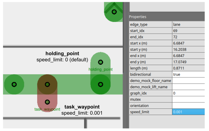
Combining Strategies
Combining the use of multiple features and strategies can help us navigate through more complicated scenarios.
Example: Maximum occupancy in two separate rooms
Consider this example:
- There are two activity rooms,
activity_room_Aandactivity_room_B, each with a maximum occupancy of one robot. - You would like robots waiting to enter either room to queue up outside, and enter only when their target room becomes vacant.
A navigation graph design to handle this scenario could look like this:
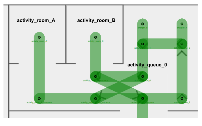
With detailed illustrations of the mutex groups and unidirectional lanes assigned:
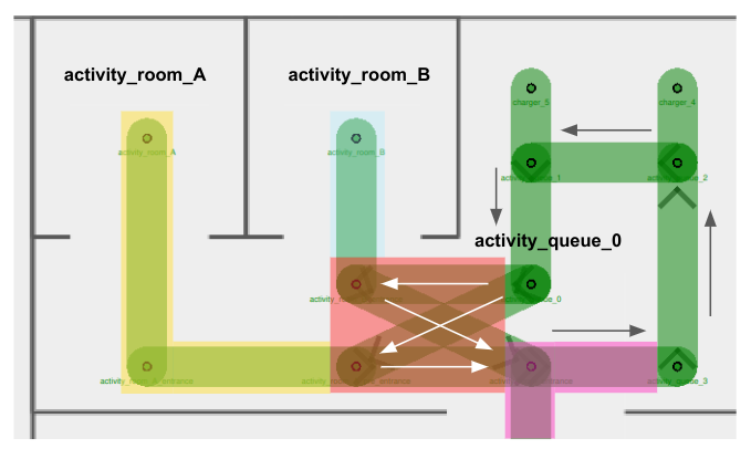
In this navigation graph,
- There are a few mutex groups present:
activity_room_A_mutexin yellowactivity_room_B_mutexin blueactivity_cross_section_mutexin redactivity_entrance_mutexin pink
- Arrows represent the direction assigned for unidirectional lanes
- Unidirectional lanes on the right of the diagram form a queue to enter either room
- Four unidirectional lanes intersect one another right outside
activity_room_B, forming a cross-section for entrance into/exit from the activity rooms- Using separate unidirectional lanes for each activity room enables the next robot to enter its target room as long as it is vacant. Otherwise, it would continue to wait outside when any room is occupied, even if its target room is empty.
- (Not shown in diagram) Lane closure logic is implemented for entrance lanes inside the cross-section area. Details are elaborated in Scenario 3 below.
This setup introduces several different possible scenarios. Let's take a look at some of the more problematic ones and how our graph strategy deals with them.
Scenario 1: Two robots exiting activity rooms at the same time
- Suppose a
robot_Acurrently occupiesactivity_room_Aand arobot_Boccupiesactivity_room_B. Both robots complete their tasks in the respective rooms and are ready to exit. robot_Aholds theactivity_room_A_mutex(in yellow), androbot_Bholdsactivity_room_B_mutex(in blue).- In order to exit, the robots would need to acquire the
activity_cross_section_mutex(in red). Depending on which robot obtains the mutex in red first, they would be allowed to travel on their respective exit lane to leave the area. Additionally, they would also need the obtain theactivity_entrance_mutex(in pink), since the exit waypoint belongs to this mutex group. - The assignment of mutex groups ensures that only one robot is travelling within the cross-section area at any time, preventing any potential crashes or conflicts.
Scenario 2: Two robots waiting to use cross-section lanes
- Suppose a
robot_Acurrently sits onactivity_queue_0, ready to enteractivity_room_Awhich is currently empty. Anotherrobot_Bis insideactivity_room_B, ready to exit. - Similar to above, the
activity_cross_section_mutex(in red) ensures thatrobot_Aandrobot_Bwill not travel on any of the cross-section lanes at the same time.
Scenario 3: Robot queueing for an occupied room
-
Suppose a
robot_Acurrently occupiesactivity_room_Aand arobot_Boccupiesactivity_room_B. Both robots complete their tasks in the respective rooms and are ready to exit. -
A third
robot_Cis sitting onactivity_queue_0, waiting to enteractivity_room_B.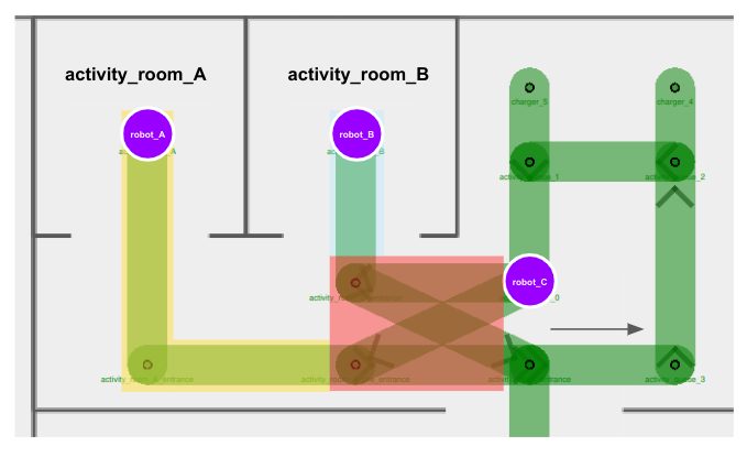
-
robot_Aholds theactivity_room_A_mutex(in yellow), androbot_Bholdsactivity_room_B_mutex(in blue). -
In order for any robot to move along to their next destination, they would need to obtain the
activity_cross_section_mutex(in red). From the scenarios above, we know that the red mutex helps to facilitate a turn-by-turn use of the cross-section lanes. -
However, if
robot_Chappens to obtain the red mutex first, all three robots would come into a deadlock, sincerobot_Aandrobot_Bwouldn't be able to obtain the red mutex untilrobot_Creleases it, butrobot_Cwouldn't be able to obtain the blue mutex in order to enteractivity_room_B, untilrobot_Breleases it.
-
Here is where lane closures could help. We can close off cross-section entry lanes when the respective activity rooms are occupied.
robot_Cwould not be able to obtain the red mutex nor proceed with its task untilrobot_Bleavesactivity_room_B.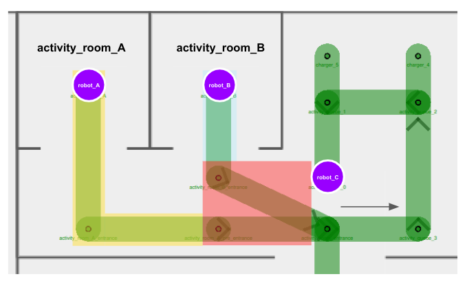
-
After
robot_Bhas successfully exited the activity room and this area altogether, the entry lane toactivity_room_Bcan be opened up again for use.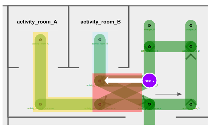
Other Considerations
Instead of implementing lane closure, why don't we assign
activity_room_B_mutex(in blue) to the entry lane towardsactivity_room_B, andactivity_room_A_mutex(in yellow) to the entry lane towardsactivity_room_A?
We want the four cross-section lanes to belong to the same mutex group, in order to ensure that only one robot travels across any of these lanes at any point of time. This prevents situations where multiple robots move near or towards each other in a cramped corridor. Since each lane can only be assigned one mutex group, we can leverage on other features, such as lane closures, to ensure that queueing robots don't enter the cross-section if their target room is occupied.